


Knowledge Base
Types of Welding Joints and When to Bevel Them
The five basic types of welding joints are the butt, tee (T), corner, lap and edge joint, as named in AWS A3.0. A joint describes how the parts meet; the weld type describes how they are welded. Butt, tee and corner joints in thicker plate often need a beveled edge, while lap and edge joints rarely do.
TFON Machines for This Job
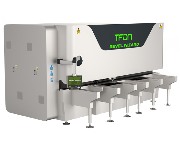
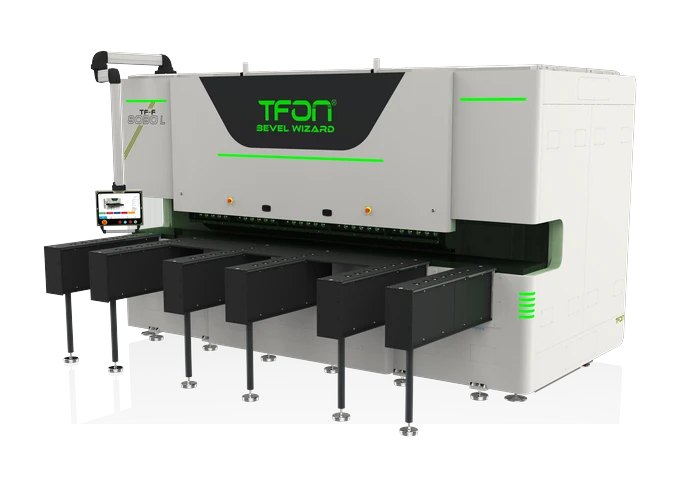
- TFON Bevel Wizard® TF-C 8010 L Plate beveling machine for 4 to 100 mm plate, parts up to 12,000 mm long, working angle -30° to +80° Specifications Request a Quote
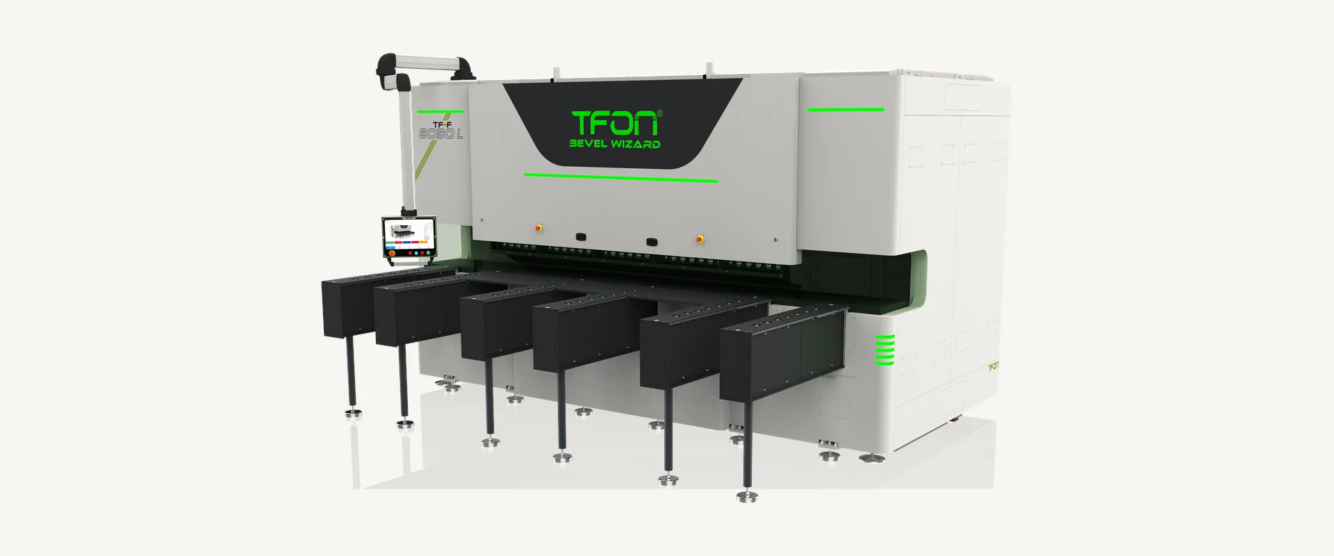
- TFON Bevel Wizard® TF-F 8030 L Plate beveling machine for small and mid-size parts, 60 to 3,000 mm long, 4 to 100 mm thick Specifications Request a Quote
The Five Basic Types of Welding Joints
There are five basic types of welding joints: the butt joint, the T-joint (tee joint), the corner joint, the lap joint and the edge joint. AWS A3.0, the American standard for welding terms, defines each one by how the members sit relative to each other, not by the weld that joins them.
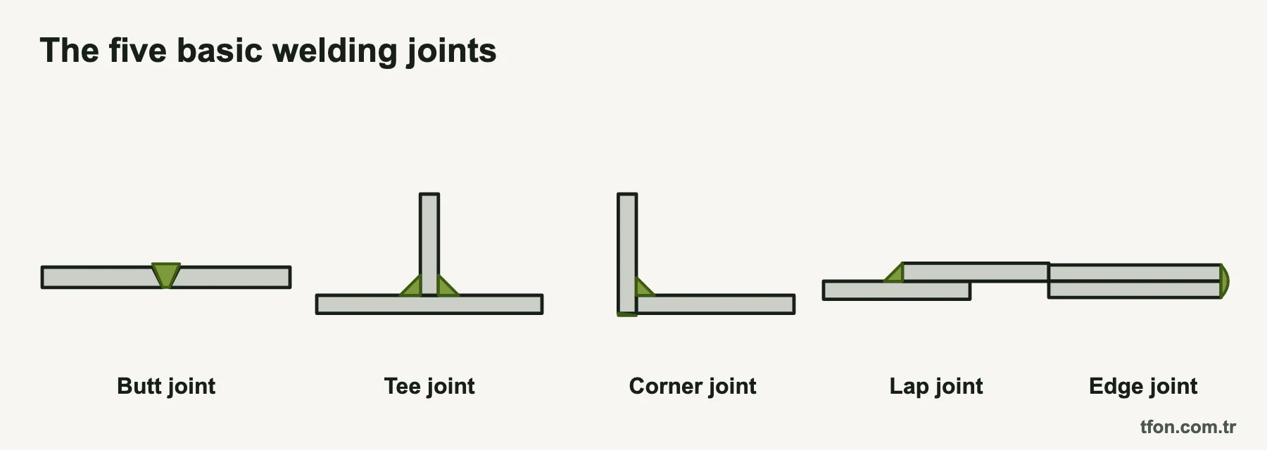
The five joints differ in where the parts touch and at what angle. The diagram of the five welding joint types on this page shows them side by side in cross-section.
- Butt joint: two members lie in roughly the same plane and meet edge to edge.
- T-joint: the edge of one member meets the face of the other at roughly a right angle, forming a T.
- Corner joint: two members meet at or near their edges at roughly a right angle, forming an L.
- Lap joint: two members overlap in parallel planes.
- Edge joint: the edges of two or more parallel or nearly parallel members are joined.
Drawings also show variants of these five. A skewed T-joint has its stem at an angle other than 90°, and two T-joints on opposite faces of one plate form a cruciform joint.
The table below summarizes the five joints of welding, the welds most often made in them and where they are typically used. Short definitions of the terms are in the welding terms glossary.
| Joint | Common weld types | Typical applications |
|---|---|---|
| Butt joint | Square, V, bevel, U and J groove welds | Plate splices, beams and girders, tanks, vessel shells |
| T-joint | Fillet welds; bevel or J groove welds, often with a reinforcing fillet | Stiffeners, brackets, web to flange, base plates |
| Corner joint | Fillet, V or bevel groove welds; edge welds on sheet | Box sections, frames, enclosures, tanks |
| Lap joint | Fillet, plug and slot welds; spot and seam welds | Sheet metal assemblies, gussets, repair plates, strap splices |
| Edge joint | Edge welds; square or bevel groove welds on the edges | Flanged thin sheet, ducts, light containers, seal welds |
Joint Type vs Weld Type
A joint type describes how the parts are arranged; a weld type describes the weld that joins them. A T-joint, for example, can be welded with two fillet welds, with a bevel groove weld from one side, or with a double-bevel groove weld that reaches complete joint penetration. The joint stays the same, while cost, strength and edge preparation change with the five weld types below.
- Groove welds: made in a groove between the members or in a prepared edge. The groove can be square, V, bevel, U, J, flare-V or flare-bevel, single or double, and designed for complete or partial joint penetration.
- Fillet welds: roughly triangular in cross-section and laid in the corner between two surfaces. They need no edge preparation.
- Plug and slot welds: made through a round hole or an elongated slot in one member of a lap or T-joint.
- Spot and seam welds: made between overlapping members, usually by resistance welding on sheet.
- Edge welds: made on the edges of an edge joint or a flanged corner.
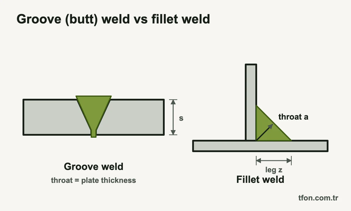
The structural difference between a groove weld and a fillet weld is the throat, the dimension that carries the load. A groove weld with complete joint penetration has a throat equal to the thickness of the thinner part. An equal-leg fillet between members at 90° has a theoretical throat of about 0.7 times its leg size. ISO drawings can state that throat directly as the a dimension, while AWS drawings give the leg size.
Watch the wording on international drawings. ISO 2553 and European practice call a groove weld a butt weld even when it sits in a T-joint, so a single-bevel butt weld may join a stiffener to a flange. AWS keeps butt for the joint and groove for the weld. The guide to weld bevel and groove types covers the groove shapes and their dimensions.
Butt Joint Welding: From Square Edges to Double-V
A butt joint joins two members that lie in approximately the same plane, and it is welded with a groove weld that passes the force straight through. Welded butt joints with complete joint penetration, ground flush where fatigue matters, are the standard splice for plate, beams and vessel shells.
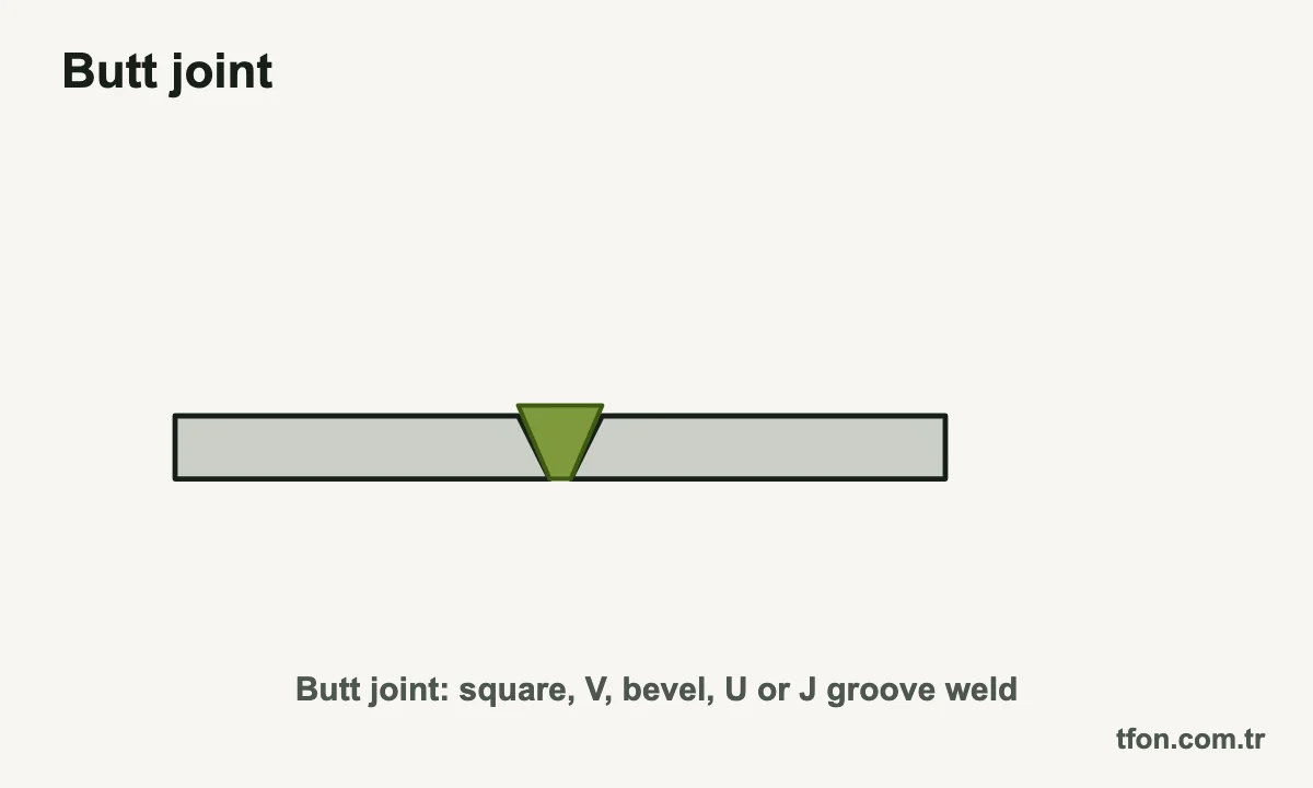
Plate thickness decides whether the edges stay square or are beveled. An arc fuses only a limited depth into a square edge, so beyond a few millimeters the edges are opened into a groove that lets the arc reach the root. ISO 9692-1, the international reference for joint preparation of steel, lists typical preparations for each thickness range. The table below condenses those ranges into a first selection guide for butt joint welding in steel.
| Plate thickness (approx.) | Welded from | Typical preparation | Why |
|---|---|---|---|
| Up to 4 mm (5/32 in) | One side | Square (I) groove with a root gap | Stick or TIG can fuse the full thickness without a bevel |
| Up to 8 mm (5/16 in) | Both sides | Square (I) groove | Each side fuses about half the thickness |
| 3 to 10 mm (1/8 to 3/8 in) | One side | Single-V groove | Opens the joint so the root can be reached from one side |
| 5 to 40 mm (3/16 to 1 1/2 in) | One side | Y groove (V with a broad root face) | The larger land supports the root pass and saves filler metal |
| Over 10 mm (3/8 in) | Both sides | Double-V (X) groove | Much less weld metal than a single V; shrinkage balanced between the faces |
| Over 12 mm (1/2 in) | One side | Single-U groove | Less weld metal than a V on thick plate; needs a machined root radius |
The ranges overlap on purpose, because process, position, access and code decide between them. They are guidance, not a procedure: the welding procedure specification (WPS) and the applicable code govern the final groove angle, root face and root opening. The reasoning behind the thickness limits is explained in why weld beveling is necessary for thick plate welding.
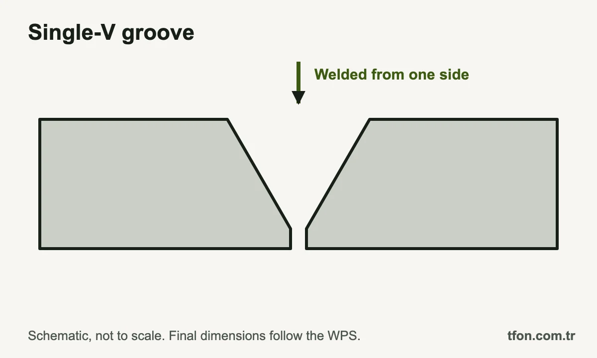
Access is the second decision. A single-V groove is welded from one side, usually onto a backing bar or with a controlled open root, and it tends to pull the plates out of flat as the groove fills. A double-V groove needs access to both faces and a back-gouged root, but it uses less weld metal and the shrinkage of one side offsets the other. When butt-welded parts differ in thickness, the thicker part is usually tapered down to the thinner one, with the slope set by the design code.
T-Joint Weld: Fillet or Bevel Groove
A T-joint, or tee joint, is welded with fillet welds in most cases and with a bevel groove weld when the stem must carry its full strength across the joint. The stem is the member whose edge meets the face of the other member: the web of a girder or the gusset of a bracket. Fillets need no preparation, which makes them the default for stiffeners, brackets and most static connections.
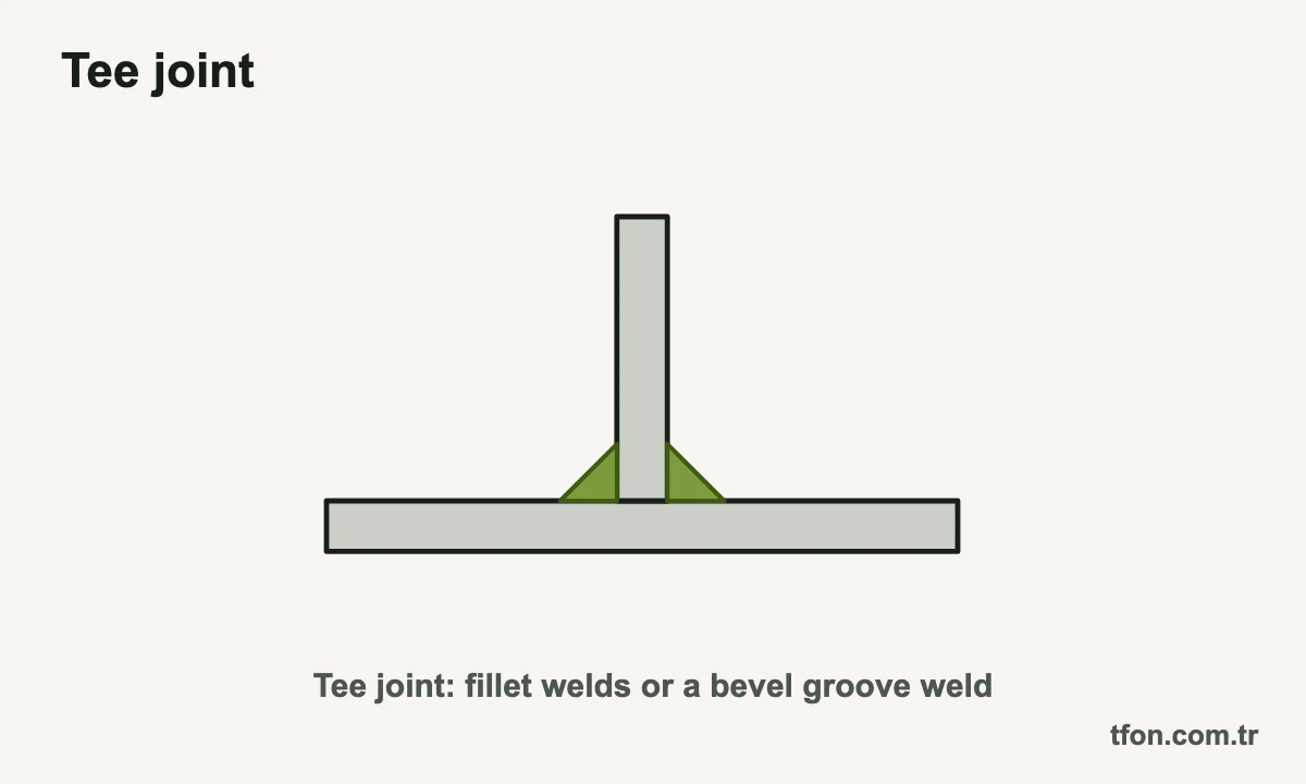
Fillet welds have a cost limit. The weld metal in a fillet grows with the square of its leg size: a 6 mm (1/4 in) fillet holds about 18 mm² of weld metal in cross-section, a 12 mm (1/2 in) fillet about 72 mm², four times as much. On thick stems, the fillets needed to develop the stem strength become so large that a groove weld uses less metal and less heat. Double fillets, one on each side of the stem, are also far more reliable than a single fillet, which can open at its root when the stem bends.
For a groove-welded T-joint weld, only the stem is prepared. A single-bevel groove is welded from one side, as a partial joint penetration weld or onto backing for complete penetration. A double-bevel (K) groove is beveled from both faces of the stem and welded from both sides with the root back-gouged. It is the usual detail for a complete joint penetration T-joint in thick plate.
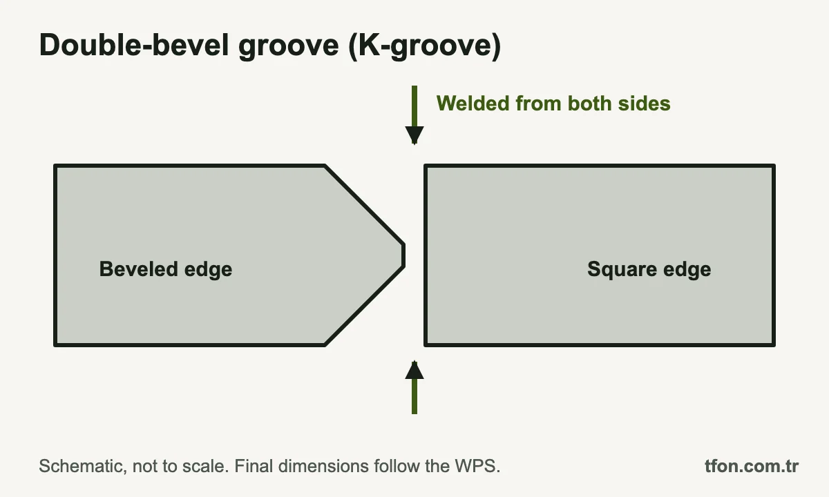
Groove welds in T-joints are commonly finished with a small reinforcing fillet that eases the change of section at the weld toe. Whether a tee needs complete or partial penetration is a design decision, covered in the guide to complete vs partial joint penetration. Skewed T-joints need extra care on the acute side, where access to the root is limited.
Corner Joint Welding: Open and Closed Corners
A corner joint joins two members that meet at roughly a right angle with their edges together, forming an L. Unlike a T-joint, the weld sits at the outside corner of the assembly, which makes corner joints the basis of box sections, frames, tanks and sheet metal enclosures. How the edges are placed decides whether corner joint welding needs any edge preparation.
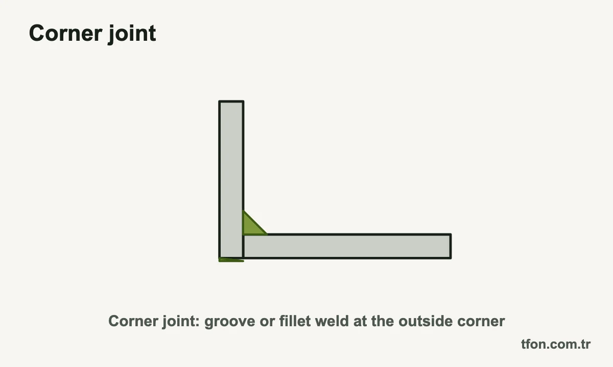
- Open corner: the plates touch only at their edges and leave a V-shaped groove on the outside. The weld fills that natural groove without beveling, which suits sheet and light plate.
- Half-open corner: one plate overlaps part of the other plate's edge. It is easier to fit than a full open corner.
- Closed corner: the edge of one plate sits flush against the face of the other. The outside is flat, so the joint is welded with a fillet on the inside or, on thicker plate, with a bevel groove on the outside.
On thick plate, a closed corner is prepared like a T-joint: the member whose edge butts against the other gets a single-bevel or J groove. Corner joints in box sections are often reachable from the outside only, so they are designed as single-sided groove welds with backing or as partial penetration welds. Weld shrinkage pulls the corner out of square, so tacks, fixtures and weld sequence are planned before the first pass.
Lap Joint Welding
A lap joint joins two members that overlap in parallel planes, and it is usually welded with fillet welds along the edges of the overlap. It needs no edge preparation and tolerates variation in part size, so lap joint welding is common in sheet metal assemblies, gussets, repair plates and splice straps. Plug and slot welds through holes in the top member add weld area where the edges alone are too short.
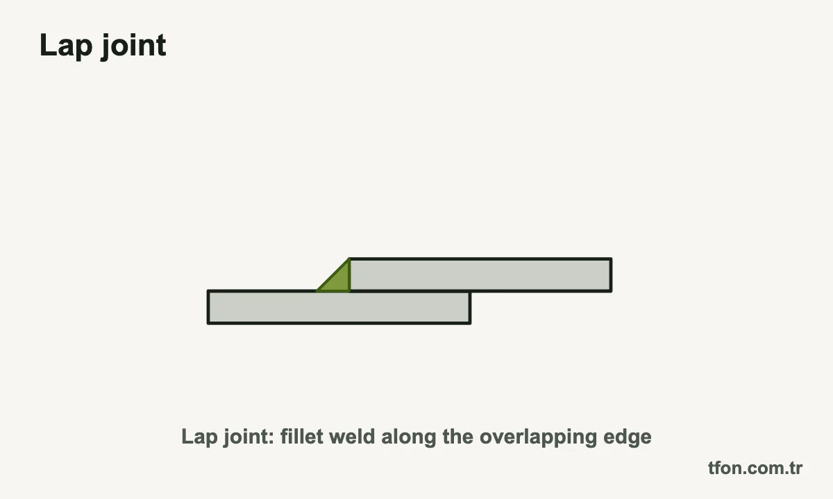
The weakness of a lap joint is its load path. The two plates are offset by their own thickness, so a tension load bends the joint, and a lap welded on one edge only can open like a hinge. Fillets on both edges of the overlap restrain that rotation and are standard for load-carrying laps. For the same reason, lap joints rate well below ground butt joints under fatigue loading.
A few rules of practice apply to most structural laps. They come from US structural practice and are worth checking against the code edition you work to.
- Overlap length: AWS D1.1 and the AISC Specification call for an overlap of at least five times the thickness of the thinner part, and not less than 25 mm (1 in), in load-carrying lap joints.
- Edge fillets: a fillet along the edge of the top plate is limited by that plate's thickness. On thicker plate it is kept slightly smaller, so the original edge stays visible for inspection.
- Crevices: the gap between overlapping plates can trap moisture, pickling acid or cleaning fluid. Seal-weld the overlap where corrosion or coating matters, and vent large overlaps before hot-dip galvanizing.
Edge Joint Welding
An edge joint joins the edges of two or more parallel or nearly parallel members, and the weld is made along those edges. It is a sheet metal joint more than a structural one: flanged edges of thin sheet, ducts, light containers and seams that only need to seal. On thin sheet, the edges are often melted together by TIG welding with little or no filler metal.
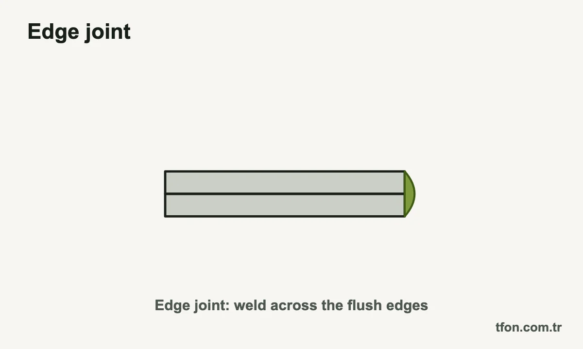
Thicker members in an edge joint can be grooved with a square, bevel, V, J or U preparation along their edges. Even so, the weld sits at the edge while the members continue side by side, so any load that pulls the plates apart puts the weld root in tension. Edge joints are therefore avoided where the joint carries significant tension, bending or cyclic load. If an edge joint turns up in a load-carrying position during design review, a butt, T- or lap joint usually carries the load more directly.
How to Choose a Welding Joint
Choose a welding joint by working through the load, the plate thickness, access to both sides, distortion and the cost of preparing the edges. The part geometry often fixes the joint family: members in one plane meet in a butt or lap joint, members at an angle in a T- or corner joint. Within that family, load and thickness decide the weld and the edge preparation.
The ratings below are relative and assume steel plate joined by arc welding. The table compares the joints on the criteria that usually decide the choice.
| Joint and weld | Typical thickness | Load and fatigue | Access needed | Distortion | Preparation cost |
|---|---|---|---|---|---|
| Butt joint, CJP groove | Any; square edges only on thin plate | In-line load path; good fatigue when ground flush | One side with backing, or both sides | Moderate; higher with a single-V | Bevel above the square-edge limit |
| T-joint, double fillet | Any; fillets grow large on thick stems | Good static capacity; root and toes limit fatigue | Both sides of the stem | Low to moderate; flange can pull | None |
| T-joint, CJP double-bevel | Thick stems | Full stem strength; good fatigue | Both sides, plus back gouging | Moderate, balanced | Double bevel on the stem |
| Corner joint | Sheet to thick plate | Moderate; check through-thickness pull | Mostly outside | Corner angle can move | None on open corners; bevel on thick closed corners |
| Lap joint, double fillet | Mostly sheet and light plate | Offset load path; low fatigue rating | Both edges of the overlap | Low | None |
| Edge joint | Mostly thin sheet | Root opens under load; light duty | Edge only | Low | None on sheet; groove on thicker plate |
A practical sequence works for most fabrication drawings. Each step narrows the choice made in the step before.
- Define the load: magnitude, direction relative to the weld, static or cyclic.
- Let the geometry choose the joint family, then pick the weld that carries the load with the least weld metal.
- Compare thickness with the square-edge limit to see whether a bevel is needed.
- Check access: with one side only, plan backing or a single-sided groove.
- Check inspection: a weld that needs ultrasonic or radiographic testing needs a geometry that allows it.
- Weigh the cost of beveling against the extra welding time of a larger fillet.
Edge Preparation by Joint Type
Butt joints above the square-edge limit, groove-welded T-joints and thick closed corners need a beveled edge, while lap joints and most edge joints need only clean, straight edges. The table below shows which member is prepared in each case and when a bevel becomes necessary.
| Joint | Weld | Member prepared | Typical preparation | Bevel needed when |
|---|---|---|---|---|
| Butt | Groove | Both members (V, X, U) or one (bevel, J) | Single-V, Y, double-V, single-bevel | Thickness exceeds the square-edge limit |
| T-joint | Fillet | None | Square edge, tight fit-up | Not needed |
| T-joint | Groove, CJP or PJP | Stem only | Single-bevel, double-bevel (K), J | The design calls for a groove weld |
| Corner, open | Groove in the natural V | None | Square edges | Rarely |
| Corner, closed | Fillet or groove | Butting member | Single-bevel or J | Outside groove weld on thicker plate |
| Lap | Fillet, plug or slot | None, or holes for plug and slot welds | Clean, flat contact faces | Not needed |
| Edge | Edge or groove | Both edges | Square or flanged on sheet; bevel or V on plate | Thicker members |
On single-bevel and J grooves, the drawing must show which member gets the bevel. In AWS A2.4 the arrow points to that member, with a break in the arrow line where it is not obvious, as explained in the welding symbols chart. Beveling the flange instead of the web is a mistake that is expensive to correct after cutting.
Edge condition matters as much as geometry. Thermally cut edges carry slag, dross and an oxide layer that can end up in the root, so plasma and oxy-fuel cut parts are cleaned before or during beveling. Straight bevels for V, Y, single-bevel, double-V and double-bevel grooves can be produced on a plate beveling machine with a repeatable angle and root face along the full edge.
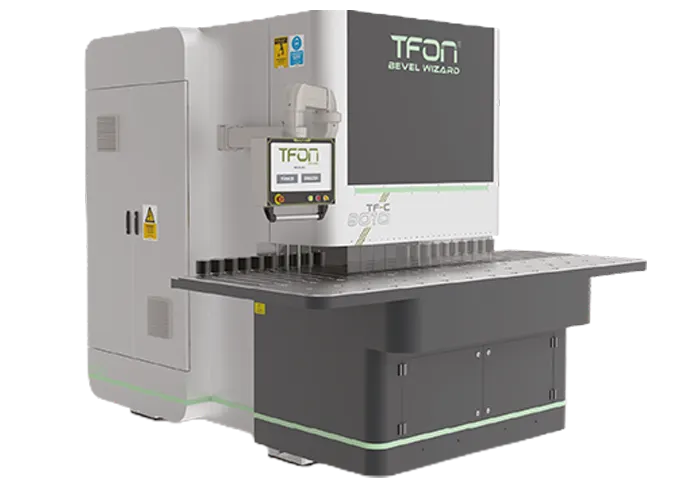
TFON Bevel Wizard machines bevel plate and sheet from 4 to 100 mm thick at a working angle of -30° to +80°. The Bevel Wizard TF-C 8010 L has a sliding table for parts up to 12,000 mm long, and the TF-F 8030 L has a fixed table for parts 60 to 3,000 mm long. J and U grooves need a root radius, which is usually machined, so discuss them with TFON before planning them on a straight-bevel machine. For the process overview, see weld bevel preparation.
Common Joint Design Mistakes
Most welded joint problems are fixed on the drawing, not in the shop. The mistakes below appear again and again in fabrication drawings, and each one costs weld metal, distortion or a failed inspection.
- Specifying CJP by default: a complete penetration groove weld where a fillet or partial penetration weld would carry the load adds beveling, back gouging, weld metal and testing.
- Single-sided welds under bending: a single fillet on a T-joint or a lap welded on one edge can open at the root. Weld both sides where the joint bends.
- Single-V on thick plate that can be turned: it needs nearly twice the weld metal of a double-V and distorts more.
- No access for the welder: a groove inside a closed box or a fillet in a tight acute angle cannot be welded properly. Check torch access at the design stage.
- Bevel angle confused with groove angle: beveling each plate of a 60° V-groove to 60° doubles the groove angle and roughly triples the weld metal. State which angle the drawing means.
- Through-thickness pull on thick plate: large welds on T- and corner joints load the face plate through its thickness, which can cause lamellar tearing in susceptible steel. Keep welds no larger than needed and consider steel with guaranteed through-thickness properties.
- Loose fit-up on fillet welds: a gap between stem and face reduces the effective throat. Codes such as AWS D1.1 limit that gap and require a larger leg when it exceeds a small value.
Every weld also leaves residual stress and some distortion. Where dimensional stability or service conditions demand it, the guide on stress relief after welding explains the options.
TFON Machines for This Job
-
TFON Bevel Wizard® TF-C 8010 L
Plate beveling machine for 4 to 100 mm plate, parts up to 12,000 mm long, working angle -30° to +80°
Specifications Request a Quote -
TFON Bevel Wizard® TF-F 8030 L
Plate beveling machine for small and mid-size parts, 60 to 3,000 mm long, 4 to 100 mm thick
Specifications Request a Quote
Frequently Asked Questions
What are the 5 types of welding joints?
The five types of welding joints are the butt joint, T-joint, corner joint, lap joint and edge joint. AWS A3.0 defines them by how the members are positioned, not by the weld used. Each joint can take several weld types, such as groove or fillet welds.
What is the difference between a butt joint and a butt weld?
A butt joint is a joint type: two members meeting edge to edge in one plane. In ISO and European usage, a butt weld is a groove weld, and it can also be made in a T- or corner joint. AWS calls the weld a groove weld and keeps the word butt for the joint.
When does a butt joint need a bevel?
A butt joint needs a bevel once the plate is too thick for the arc to fuse a square edge through its thickness. ISO 9692-1 lists square edges for stick and TIG welding up to about 4 mm from one side and about 8 mm from both sides. Above that, V, Y or double-V grooves are typical, and the WPS sets the final values.
Should a T-joint be fillet welded or groove welded?
Most T-joints are fillet welded, because fillets need no edge preparation and carry static loads well. A bevel groove weld is used when the stem must develop its full strength in tension, under fatigue loading, or when the required fillets would be very large. A double-bevel groove with back gouging is the usual detail for a complete penetration T-joint.
What is the difference between an open and a closed corner joint?
In an open corner joint, the plates meet only at their edges and leave a V-shaped groove on the outside that the weld fills. In a closed corner joint, the edge of one plate sits flush against the face of the other. Closed corners are fillet welded inside or, on thicker plate, beveled for a groove weld on the outside.
How much overlap does a lap joint need?
For load-carrying lap joints, US structural practice calls for an overlap of at least five times the thickness of the thinner part, and not less than 25 mm (1 in). Both edges of the overlap should be fillet welded to keep the joint from opening under load. Sheet metal laps joined by spot welding follow their product standard.
Which type of welding joint is strongest?
No joint type is strongest in every case, because strength depends on the weld, the load direction and the thickness. A butt joint with a complete joint penetration groove weld has an in-line load path and, with matching filler metal, develops the full strength of the thinner plate. Lap and edge joints carry load less directly and suit lighter work.
Let Us Review Your Part
Share the material, cutting method, part dimensions and the next operation, with photos of both faces. We will recommend the machine and station sequence that fits the part.