


Knowledge Base
What Is Beveling in Welding? Bevel and Groove Types
Beveling in welding is the preparation of a plate or sheet edge at a defined angle so that two parts form a groove the welder can fill with full penetration. The main groove types are V, X, Y, K, J and U, and each is defined by its bevel angle, root face and root gap.
TFON Machines for This Job
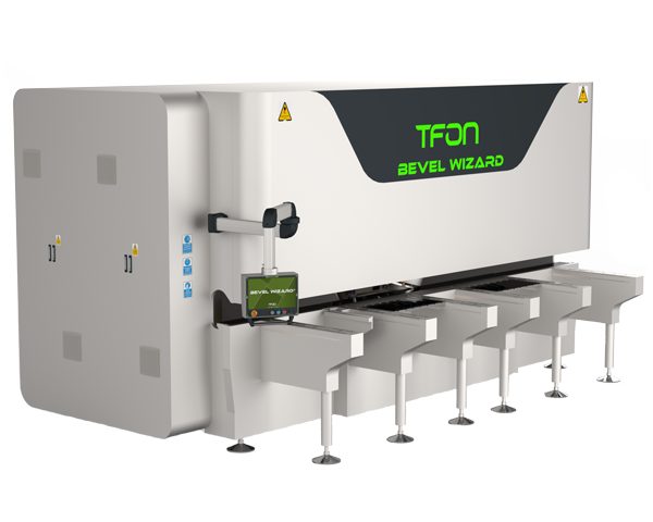
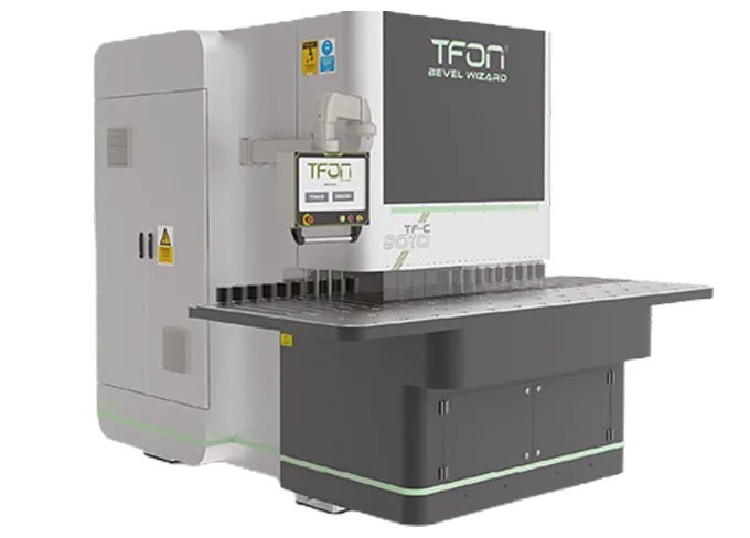
- TFON Bevel Wizard® TF-C 8010 L Plate beveling machine for 4 to 100 mm plate, parts up to 12,000 mm long, working angle -30° to +80° Specifications Request a Quote
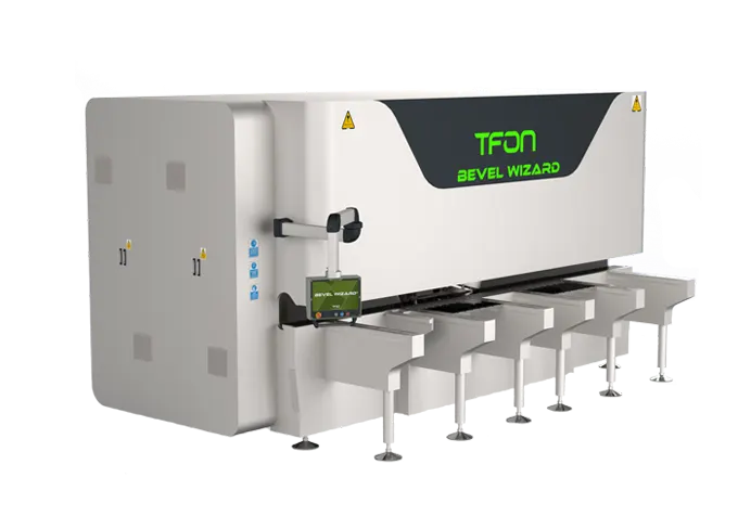
- TFON Bevel Wizard® TF-F 8030 L Plate beveling machine for small and mid-size parts, 60 to 3,000 mm long, 4 to 100 mm thick Specifications Request a Quote
What Is Beveling in Welding and Why Is It Done?
Beveling in welding means cutting or grinding the edge of a plate, sheet or pipe to a defined angle before the parts are joined. Two beveled edges placed together form a groove. The welder fills that groove with weld metal, and the geometry of the groove decides how the arc reaches the root and how much metal the joint needs.
The reason is access. A welding arc penetrates only so deep into a square edge. On thin sheet, two square edges with a small gap can be fused through their full thickness. On thicker plate, a square edge leaves unfused metal in the middle of the joint, which is a defect under load. Beveling opens the joint so the root can be reached and every layer can fuse with the sidewalls. ISO 9692-1, the international reference for joint preparation of steels, lists square preparations for stick and TIG welding only up to about 4 mm from one side and about 8 mm from both sides. Thicker square joints appear there only with backing, wide gaps or beam welding.
Beveling also controls weld volume. A wider groove is easier to reach but needs more filler metal, more passes and more heat input, which raises cost and distortion. A narrower groove saves metal but is harder to weld and can trap slag between passes. Groove choice is a balance between access, volume and the welding process.
A bevel for welding is not the same as a chamfer or an edge break. A chamfer or a small radius removes a sharp corner for handling or coating. A weld bevel creates a specified joint face with an angle, a root face and a relationship to the mating part. For the process view, see bevel weld preparation.
What Is a Groove Weld?
A groove weld is a weld made in a groove between two workpieces or in a prepared groove on a workpiece. In AWS terminology, the groove can be square (no bevel), V, bevel, U, J, flare-V or flare-bevel. Groove welds are usually full-penetration or partial-penetration butt or corner welds, as opposed to fillet welds, which are laid in the corner between two surfaces without edge preparation.
"Bevel weld" is shop language for a bevel-groove weld: a groove weld in which only one of the two members is beveled and the other keeps a square edge. It is common in T-joints and corner joints, where the square member butts against the face of the beveled one, and in butt joints where only one part can be prepared.
A few terms from AWS A3.0, the American standard for welding terms, keep the discussion precise:
- Bevel angle: the angle between the bevel of one member and a plane perpendicular to its surface.
- Groove angle: the total included angle of the groove between the workpieces. On a symmetrical V-groove it is twice the bevel angle; on a single-bevel groove it equals the bevel angle.
- Root face (land): the portion of the groove face at the joint root that is left unbeveled.
- Root opening: the separation between the workpieces at the joint root. ISO documents call it the root gap.
ISO documents use the same geometry with Greek letters: α for the included groove angle, β for the bevel angle of one member, b for the gap and c for the root face. Keeping bevel angle and groove angle apart prevents the most common drawing error in weld preparation, a V-groove beveled to the full included angle on each plate.
Weld Bevel and Groove Types: V, X, Y, K, J and U
The groove letters describe the shape of the prepared joint seen in cross-section.
- V-groove (single-V): both edges beveled, welded from one side. The standard preparation for plate in the lower thickness range when access is from one side only.
- Y-groove: a V-groove with a broad root face. The thicker land supports the root pass and reduces burn-through, and it takes less filler metal than a plain V at the same thickness.
- X-groove (double-V): both edges beveled from both faces, welded from both sides. On thicker plate it needs roughly half the weld metal of a single V and balances shrinkage between the two sides, which reduces angular distortion. It requires access to both faces and usually back-gouging or a clean root on the second side.
- Single-bevel (half V): one member beveled, the other square. Used for T-joints and corner joints and where only one part can be prepared.
- K-groove (double-bevel): one member beveled from both faces. The standard full-penetration preparation for thicker T-joints welded from both sides.
- U-groove: both edges prepared with a curved root and steep sidewalls. On thick plate it needs less weld metal than a V, at the cost of more demanding preparation.
- J-groove: the single-member version of the U, one edge curved and the other square. Used on thick T-joints and corner joints.
Double-U and double-J grooves apply the same idea to very thick plate welded from both sides.
The trade-off runs through the list. V, Y, bevel, X and K grooves are straight angled faces, which plate beveling machines, thermal cutting heads and grinders produce directly. U and J grooves save weld metal on thick sections but need a root radius, which is usually machined. They pay off where weld volume dominates cost, typically on heavy plate and long seams.
Typical Groove Dimensions per ISO 9692-1
ISO 9692-1 collects joint preparations for manual metal arc (stick), gas-shielded metal arc (MIG/MAG), gas, TIG and beam welding of steels. Its ranges are design guidance based on experience, not manufacturing tolerances, and the standard itself notes that its examples are not the only possible solutions.
| Groove | Welded from | Plate thickness t | Angle | Root gap b | Root face c |
|---|---|---|---|---|---|
| Square (I), stick or TIG | One side | up to 4 mm | none | about t | none |
| Square (I), stick or TIG | Both sides | up to 8 mm | none | about t/2 | none |
| Single-V | One side | over 3 up to 10 mm | α 40° to 60° | up to 4 mm | up to 2 mm |
| Y (V with broad root face) | One side | 5 to 40 mm | α about 60° | 1 to 4 mm | 2 to 4 mm |
| Single-bevel (half V) | One side | over 3 up to 10 mm | β 35° to 60° | 2 to 4 mm | 1 to 2 mm |
| Single-U | One side | over 12 mm | β 8° to 12° | up to 4 mm | up to 3 mm |
| Single-J | One side | over 16 mm | β 10° to 20° | 2 to 4 mm | 1 to 2 mm |
| X (double-V) | Both sides | over 10 mm | α about 60°; 40° to 60° for MIG/MAG | 1 to 3 mm | up to 2 mm |
| K (double-bevel) | Both sides | over 10 mm | β 35° to 60° | 1 to 4 mm | up to 2 mm |
How to read the table:
- The thickness ranges are the ranges for which the standard lists each preparation. As a rough US equivalent, 10 mm is about 3/8 in, 12 mm about 1/2 in and 16 mm about 5/8 in.
- Root gaps refer to the gap after tack welding, where tacks are used.
- U and J preparations also carry a root radius; for the single-U preparation with a V root, ISO 9692-1 gives 6 to 9 mm.
- The standard also asks for the edges of the root face to be deburred, and allows them to be chamfered by up to 2 mm.
These are typical values, not a procedure. The welding procedure specification (WPS) and the applicable code govern the final values. In US structural work, AWS D1.1 lists prequalified groove joint details with their own dimensions and tolerances; pressure equipment is welded under procedures qualified to ASME Section IX. Use this table to understand the geometry and to check a drawing for plausibility, then take the numbers from the qualified procedure.
What Bevel Angle Should You Use?
The bevel angle follows from the groove type, the thickness, the welding process and the position, and the WPS states it. Within that, a few relationships hold everywhere.
Bevel angle and groove angle
On a symmetrical V or X groove, each plate carries half the included angle. A 60° included groove means a 30° bevel on each edge. On single-bevel and K grooves, only one member is beveled, so the groove angle equals the bevel angle, which is why the ISO ranges for those grooves (35° to 60°) are larger per edge than for a V.
Process and position
ISO 9692-1 lists an included angle of about 60° for several preparations welded with covered electrodes or TIG, and allows 40° to 60° for MIG/MAG on the double-V. Processes with a narrow, deep-penetrating arc can work with a narrower groove. Out-of-position welding and difficult access may need a wider one.
What changes when the angle changes
- Too narrow: the arc cannot reach the sidewalls and root; risk of lack of fusion, incomplete penetration and trapped slag.
- Too wide: more filler metal, more passes, more heat input and more distortion, with no gain in strength.
- Inconsistent along the edge: the welder has to change technique along the seam, and the fill varies. Hand-ground bevels on long plates are prone to this.
The TFON article on how bevel angle affects weld quality covers these effects on penetration, filler consumption and distortion in more depth. The practical conclusion is the same: the goal is not a particular angle but the specified angle, repeated exactly along the whole edge and from part to part.
Root Face and Root Opening
The root is where most weld preparation problems show up, and two dimensions define it.
The root face, or land, is the unbeveled strip left at the bottom of the prepared edge. It supports the root pass and prevents burn-through. Too large a root face and the root pass cannot penetrate it; too small and the root melts through or sags. It is set when the edge is prepared, so it belongs to the beveling operation and is checked along the edge like the angle.
The root opening or root gap is the space between the parts at the root after fit-up. The beveling machine does not set it. It is created when the parts are assembled and tacked, and the WPS gives its range. A consistent bevel and root face make a consistent gap possible; they do not guarantee it.
Edge condition matters as much as dimensions. Dross, slag or a burr on the root face changes the effective land and the gap at that point, and oxide from a thermal cut can end up in the root. That is why ISO 9692-1 asks for the root face edges to be deburred. On thermally cut plate, remove slag before or during beveling; the guide on slag vs dross explains the removal options.
Groove Weld Symbols: AWS A2.4 and ISO 2553
On a drawing, the groove type is shown by a weld symbol. In the US, symbols follow AWS A2.4; most other countries use ISO 2553. The basic groove shapes are drawn much the same way in both, but the names and the side conventions differ.
| Preparation | AWS A2.4 / A3.0 name | ISO 2553 name | Common shop name |
|---|---|---|---|
| Square edge | Square-groove weld | Square butt weld | I-joint, square butt |
| Both edges beveled | V-groove weld | Single-V butt weld | V-groove |
| V with a large land | V-groove weld with root face | Single-V butt weld with broad root face | Y-groove |
| One edge beveled | Bevel-groove weld | Single-bevel butt weld | Bevel weld, half V |
| Both edges curved | U-groove weld | Single-U butt weld | U-groove |
| One edge curved | J-groove weld | Single-J butt weld | J-groove |
| V from both sides | Double-V-groove weld | Double-V butt weld | X-groove |
| Bevel from both sides | Double-bevel-groove weld | Double-bevel butt weld | K-groove |
Arrow side and other side
In AWS A2.4, a symbol below the reference line applies to the arrow side of the joint and a symbol above it to the other side. Symbols on both sides describe a double groove, such as a double-V (X) or double-bevel (K). For single-bevel and J grooves, the arrow points toward the member that is prepared, with a break in the arrow line where this is not obvious.
ISO 2553 offers two systems. System A uses a continuous reference line with a dashed identification line: a symbol on the continuous line applies to the arrow side, one on the dashed line to the other side. System B uses a single reference line, similar to the AWS convention. Check which system a drawing uses before reading the side.
Dimensions on the symbol
Both standards place the groove angle, root opening and depth of preparation next to the symbol. If a drawing shows only the symbol, the dimensions come from the WPS or a referenced joint detail. When drawings come from abroad, confirm whether the angle given is the included groove angle or the bevel angle per member before setting a machine.
Which Reference Is the Bevel Angle Measured From?
A bevel angle is only meaningful with its reference. Welding standards measure the bevel angle from a plane perpendicular to the plate surface, that is, from the square edge. A 30° bevel in that convention is a face tilted 30° away from the square edge. Measured from the plate surface instead, the same face is at 60°.
Machines, protractors and CAD programs do not all use the same reference. Before production, confirm three things:
- which reference the drawing or WPS uses;
- which reference the machine setting uses;
- whether the value is a bevel angle per member or an included groove angle.
Then check the first part with a bevel protractor or a weld gauge at defined positions: near both ends and at intervals along the edge. Measure the root face at the same points. Record the instrument and the reference with the result, so the next check uses the same basis.
Long plates need special attention. A hand-ground bevel can start at the right angle and drift over several meters, and warped plate changes the angle relative to the table. Where flatness is a problem, straighten the plate on a leveling machine before beveling.
Beveling Plate and Sheet by Machine
Plate edges are beveled by thermal cutting with tilted torches, by milling or planing heads, by grinding, and by abrasive belt beveling machines. The machine choice depends on edge length, thickness, the groove type and how consistent the result must be.
TFON builds plate and sheet beveling machines under the Bevel Wizard name. They prepare straight edges with an abrasive belt running over a Ø400 mm drum at a belt speed of 30 m/s, for plate from 4 to 100 mm thick (about 5/32 in to 4 in). The published working angle range is -30° to +80°, which lets the machine be set to the bevel angle defined in the WPS; confirm how the machine's angle reference maps to your drawing during the first trial.
- The TF-C 8010 L uses a sliding table for long straight edges, on parts from 400 to 12,000 mm long and 250 to 1,250 mm wide, at a feed rate of 1.0 to 4.0 m/min.
- The TF-F 8030 L is designed for small and mid-size parts, from 60 to 3,000 mm long and 100 to 1,250 mm wide, with a platform rated for 3,000 kg.
Bevel Wizard machines are built for plate and sheet edges. They are not pipe beveling machines. Straight bevels for V, Y, single-bevel, X and K preparations are angle settings on such a machine; J and U grooves need a root radius, so discuss those preparations with TFON before planning them on a straight-bevel machine.
Beveling and deburring are separate operations. The bevel creates a specified face; deburring removes unwanted material. A part may need both, at different stages. The plate beveling machines page compares both models.
TFON Machines for This Job
-
TFON Bevel Wizard® TF-C 8010 L
Plate beveling machine for 4 to 100 mm plate, parts up to 12,000 mm long, working angle -30° to +80°
Specifications Request a Quote -
TFON Bevel Wizard® TF-F 8030 L
Plate beveling machine for small and mid-size parts, 60 to 3,000 mm long, 4 to 100 mm thick
Specifications Request a Quote
Frequently Asked Questions
What is the difference between a bevel and a chamfer?
A weld bevel is a specified joint face with a defined angle and root face, prepared so a groove weld can reach full penetration. A chamfer is a small angled cut that removes a sharp corner for handling, assembly or coating. The geometry can look similar, but the purpose and the tolerances differ.
Is an X groove the same as a double-V groove?
Yes. X-groove is the common European and shop name for a double-V butt weld, where both edges are beveled from both faces and the joint is welded from both sides. In AWS terminology it is a double-V-groove weld. A K-groove, by contrast, is a double-bevel groove with only one member beveled.
When is a J or U groove used instead of a V groove?
On thick plate, where a V-groove would need a large volume of weld metal. The curved root and steep sidewalls of U and J grooves reduce filler metal, passes and heat input. They need more demanding preparation, usually machining, so they pay off mainly on heavy sections and long seams.
Does a beveling machine set the root gap?
No. The machine prepares the edge: the bevel angle and the root face. The root gap is created when the parts are fitted up and tacked, and its range comes from the welding procedure. A consistent bevel makes a consistent gap easier to achieve but does not set it.
Can the Bevel Wizard bevel pipe?
No. TFON Bevel Wizard machines are built for straight edges on plate and sheet, from 4 to 100 mm thick. Pipe ends need pipe beveling equipment that rotates around or with the pipe, which TFON does not build.
Let Us Review Your Part
Share the material, cutting method, part dimensions and the next operation, with photos of both faces. We will recommend the machine and station sequence that fits the part.