


Knowledge Base
Welding Symbols Chart and How to Read Weld Symbols
A welding symbol is the drawing shorthand that tells the shop which weld to make, on which side of the joint and to what size. This welding symbols chart explains weld symbols to AWS A2.4 and ISO 2553: reference line, arrow side, fillet and groove weld symbols, dimensions, supplementary symbols and the tail, with worked examples.
TFON Machines for This Job
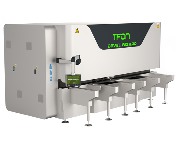
- TFON Bevel Wizard® TF-C 8010 L Plate beveling machine for 4 to 100 mm plate, parts up to 12,000 mm long, working angle -30° to +80° Specifications Request a Quote
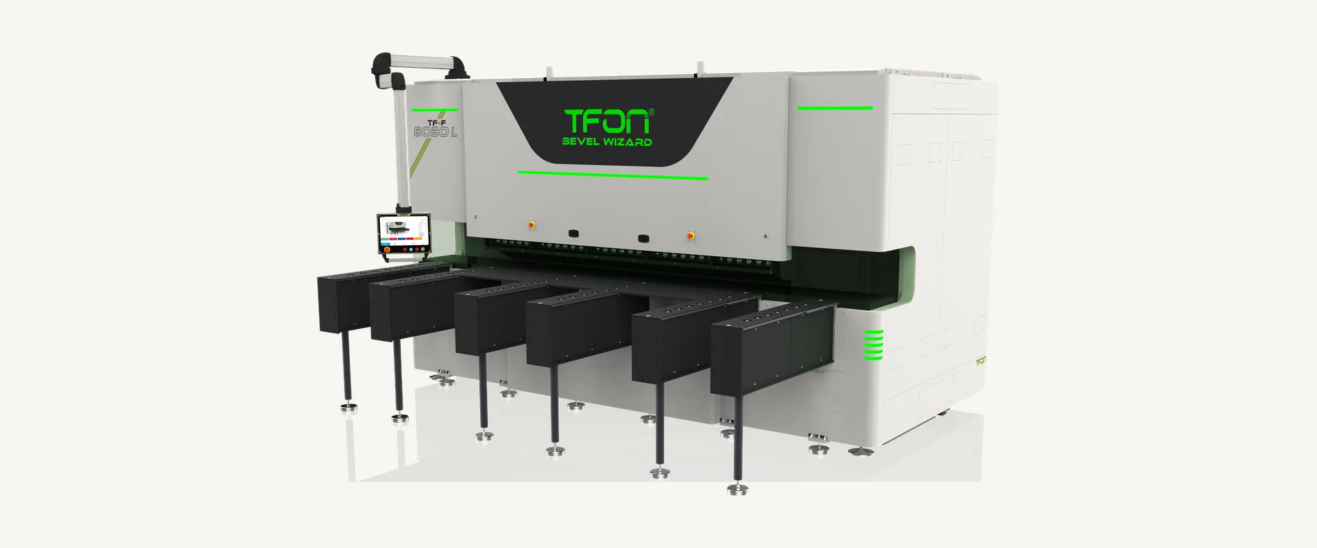
- TFON Bevel Wizard® TF-F 8030 L Plate beveling machine for small and mid-size parts, 60 to 3,000 mm long, 4 to 100 mm thick Specifications Request a Quote
Welding Symbols Chart: How to Use It
A welding symbols chart puts the basic weld symbols, the side rules and the dimension positions on one page, so you can decode a drawing without opening the standard. The chart below follows AWS A2.4, the US standard for welding, brazing and nondestructive examination symbols, and marks where ISO 2553 differs. It is also available as a free PDF to print for the shop floor or the inspection office.
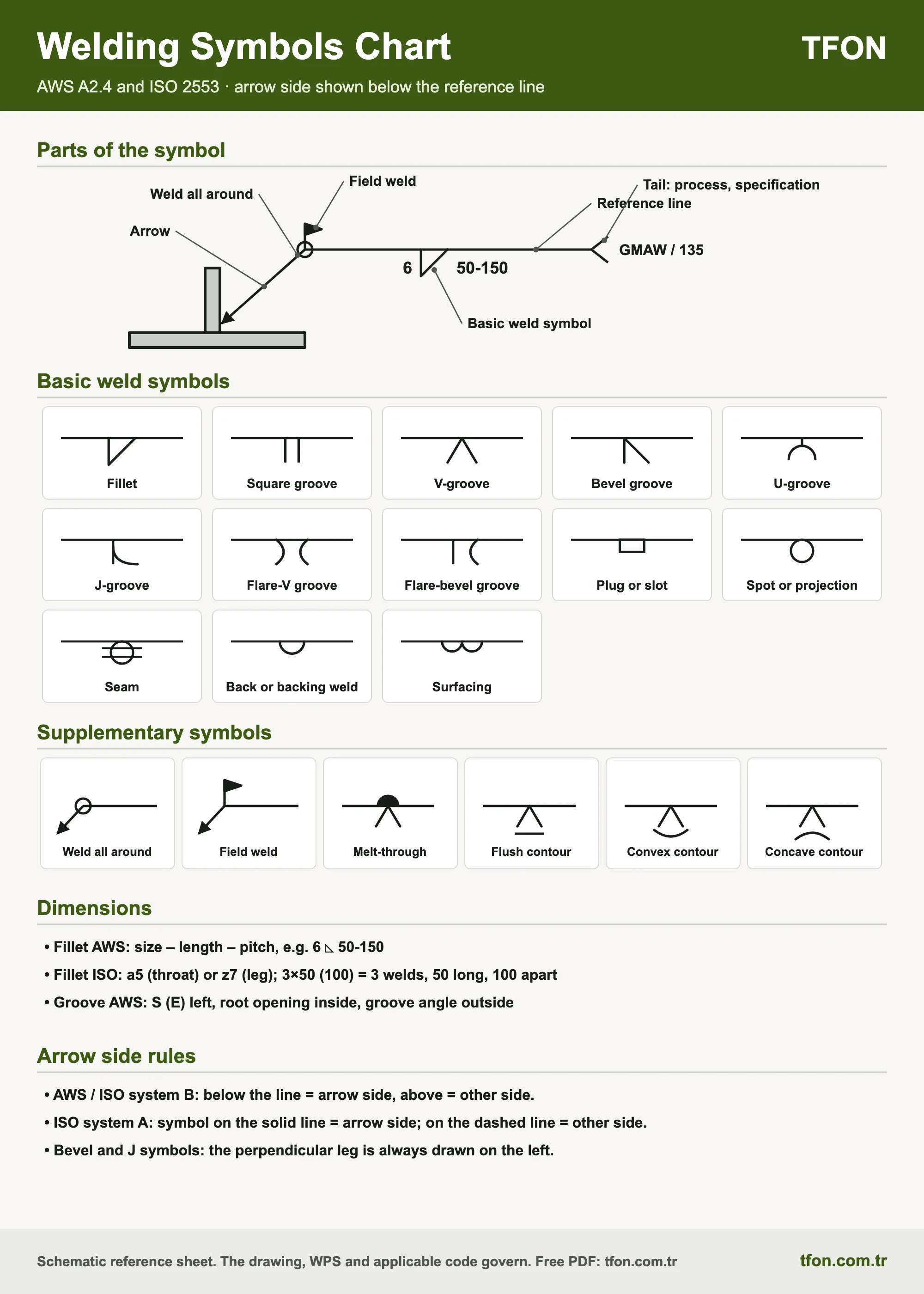
The chart follows the order in which you read a symbol. Check the title block or general notes of the drawing first, because they should state whether AWS A2.4 or ISO 2553 applies.
- Find the arrow. The side of the joint it touches is the arrow side.
- Identify the system. A dashed line beside the reference line means ISO 2553 system A. A single solid line means AWS A2.4 or ISO 2553 system B.
- Locate the weld symbol and note the side, or the line, it sits on.
- Read the dimensions: cross-section values on the left, length and spacing on the right.
- Check the supplementary symbols and the tail for all-around, field, contour, finishing, process and specification data.
The chart is a reading aid, not a design reference. Weld designers work from the current edition of the standard and the governing code, such as AWS D1.1 for structural steel.
Parts of a Welding Symbol
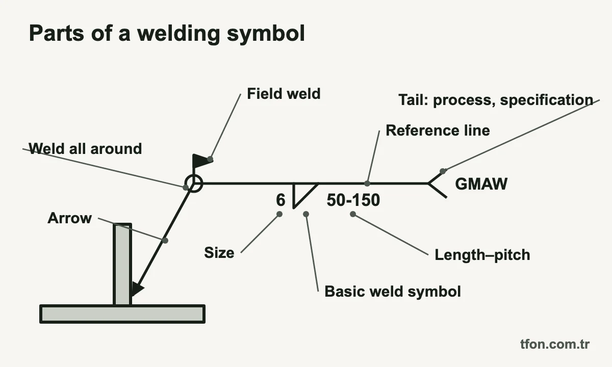
A welding symbol has up to eight elements: reference line, arrow, basic weld symbol, dimensions and other data, supplementary symbols, finish symbols, tail, and the specification, process or other reference written in the tail. Only the reference line and the arrow are always required. The diagram at the top of this page shows where each element sits.
AWS keeps two terms apart. The weld symbol is the character that shows the weld type, such as the fillet triangle. The welding symbol is the whole assembly of line, arrow, weld symbol, numbers and notes, and the welding glossary explains related terms from AWS A3.0.
- Reference line: drawn horizontally; it carries all the information.
- Arrow: links either end of the reference line to the joint. It may be bent, and one line may carry several arrows when the same weld applies at several places.
- Basic weld symbol and dimensions: the symbol sets weld type and side. Cross-section values go to its left, length and pitch to its right, root opening and groove angle at the symbol itself.
- Supplementary symbols: weld all around and field weld at the arrow junction; contour, melt-through and backing at the weld symbol.
- Tail: the open fork at the far end, holding the process, a WPS or specification number, or a note. It is left off when there is nothing to add.
Two or more stacked reference lines show a sequence of operations, and the line nearest the arrow is done first. AWS A2.4 uses the same framework for nondestructive examination symbols. The joints these symbols point to are covered in the guide to types of welding joints.
Arrow Side and Other Side in AWS A2.4
In AWS A2.4, a weld symbol below the reference line calls for a weld on the arrow side of the joint, and a symbol above the line calls for a weld on the other side. Symbols on both sides mean welds on both sides. This rule decides where the weld goes, so it is the first thing to check on any weld symbol chart.
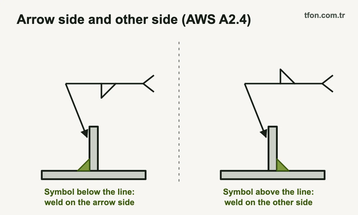
The arrow side is the side of the joint the arrow touches, and the other side is the opposite side of the same joint. On a T-joint, a fillet below the line goes on the side of the stem the arrow points to, and a fillet above it goes on the far side.
- The side rule holds whether the arrow leaves from the left or the right end of the line.
- Symbols are never mirrored. The perpendicular leg of the fillet, bevel, J and flare-bevel symbols is always drawn on the left.
- Welds without side significance, such as resistance spot and seam welds, are centered on the line.
The arrow break for bevel and J grooves
Bevel and J grooves prepare only one member, so the welding symbol must say which one. AWS A2.4 points the arrow at that member, with a definite break in the arrow line toward it, and allows the break to be omitted when the choice is obvious, such as the stem of a T-joint. For the fabricator, this break decides which plate goes to weld beveling.
Most wrong-side welds come from reading the symbol as a picture, where "above the line" seems to mean "on top of the part". The other common source is reading an ISO 2553 system A drawing with AWS habits.
The Dashed Identification Line in ISO 2553: Systems A and B
ISO 2553 system A shows the weld side with two parallel lines: a continuous reference line and a dashed identification line. A symbol on the continuous line calls for a weld on the arrow side, and a symbol on the dashed line calls for a weld on the other side. System B uses one reference line with the same below-is-arrow-side rule as AWS A2.4.
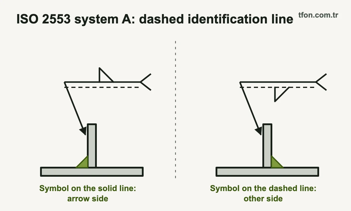
ISO 2553:1992, the basis of most older European drawings, used only the dual line. ISO 2553:2013 added a single-line method based on Pacific Rim practice, which uses the AWS side convention, and named the two methods system A and system B. ISO 2553:2019 keeps both.
How system A works
In system A, what counts is the line the symbol touches, not whether it sits above or below. The dashed line may run above or below the continuous line. A fillet standing on the continuous line is an arrow-side weld, while a fillet hanging from a dashed line underneath is an other-side weld, even though it sits below.
The dashed line is omitted for symmetrical welds, such as a double-V (X) butt weld or equal fillets on both sides. A single fillet or groove symbol with no dashed line on a system A drawing is incomplete, so ask before welding.
System B and the classic mix-up
System B reads like AWS A2.4 for the side, while the numbers follow ISO 2553 and the drawing notes. The classic error is an AWS-trained reader on a system A drawing: a fillet on top of the continuous line, with the dashed line below, means arrow side in ISO but other side to an AWS reader. The two systems should never be mixed on one drawing, so confirm the system in the title block before reading any symbol.
Basic Weld Symbols
Basic weld symbols are the small shapes that identify the weld type: fillet, groove, plug or slot, spot or projection, seam, stud, back or backing, surfacing and edge. Each is a simplified view of the weld it stands for. ISO 2553 uses the same shapes for most of them.
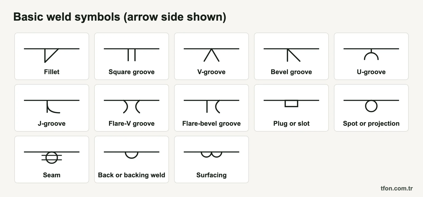
The table lists the basic weld symbols of AWS A2.4, their shapes and how their position on the reference line is read.
| Weld type | Symbol shape | Position on the reference line |
|---|---|---|
| Fillet | Right triangle, perpendicular leg on the left | Below = arrow side, above = other side |
| Square groove | Two parallel vertical lines | Below or above, as for fillets |
| V-groove | V with its point on the line | Below or above, as for fillets |
| Bevel groove | Vertical line plus one slanted line | Below or above; arrow points to the beveled member |
| U-groove | U shape | Below or above, as for fillets |
| J-groove | Vertical line plus a curve | Below or above; arrow points to the prepared member |
| Flare-V | Two arcs back to back | Below or above, as for fillets |
| Flare-bevel | Vertical line plus one arc | Below or above, as for fillets |
| Plug or slot | Rectangle | Side shows which member has the hole |
| Spot or projection | Circle | Centered for resistance spot welds |
| Seam | Circle crossed by two horizontal lines | Centered for resistance seam welds |
| Stud | Circle with an X inside | Arrow side only |
| Back or backing weld | Half-circle | Opposite the groove symbol |
| Surfacing | Row of small arcs | Arrow side only |
| Edge | Two joined edges (see chart) | Below or above, as for fillets |
Plug, slot, spot, seam, edge, stud and surfacing symbols
- Plug and slot: the weld fills a hole or slot in one member of a lap joint, and below the line the hole is in the arrow-side member. Plug diameter goes left, depth of filling inside the symbol and pitch right; with no depth shown, the hole is filled completely. Slot length, width and orientation are often given in a drawing detail.
- Spot: resistance spot welds form at the faying surface, so the circle is centered. Diameter or shear strength goes left, pitch right, and the number of spots in parentheses above or below the symbol. ISO 2553 writes the spot diameter as d.
- Seam: centered like a spot weld, with width left and length right.
- Edge: used on edge joints, where parallel or flanged sheet edges are fused together.
- Stud and surfacing: arrow side only. The stud arrow points to the surface that receives the studs, and the surfacing size on the left is the minimum build-up thickness.
Fillet Weld Symbols and Dimensions
The fillet weld symbol is a right triangle on the reference line, with its perpendicular leg always on the left. Below the line it calls for a fillet on the arrow side, above the line for the other side, and on both sides for fillets on both sides of the joint. The numbers around it set the size, length and spacing.
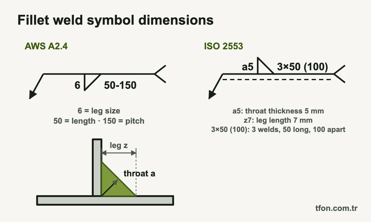
Size, length and pitch in AWS A2.4
The size, which in AWS is the leg length, goes to the left: 5/16 means a 5/16 in (about 8 mm) leg. A number to the right limits the weld length, and with no length the weld runs the full length of the joint. A double fillet carries a size on each side of the line, even when both are equal.
An unequal-leg fillet is written as two values, such as 1/4 x 3/8, and the drawing shows which leg lies on which member. For an equal-leg fillet on a 90° joint, the theoretical throat is about 0.7 times the leg.
Intermittent fillets: chain and staggered
Intermittent fillets are written as length-pitch to the right of the symbol: 2-6 means welds 2 in long, spaced 6 in center to center. Chain intermittent welds sit opposite each other, and their symbols are drawn directly opposite on the line. Staggered welds alternate from side to side, and their symbols are offset along the line.
ISO 2553: a and z
ISO 2553 puts a letter in front of the fillet size: a for the nominal throat thickness, z for the leg length. A 5 mm throat (a5) needs a leg of about 7 mm, while a 5 mm leg (z5) gives a throat of only about 3.5 mm. Many European drawings specify a, so readers used to AWS leg sizes must convert before welding or inspecting.
ISO writes intermittent welds as n × l (e): number of segments, segment length and, in parentheses, the space between segments. Because AWS pitch is measured center to center, identical numbers describe different welds in the two standards.
Groove Weld Symbols: Square, V, Bevel, U, J and Flare
Groove weld symbols show the prepared joint in miniature: two parallel lines for a square groove, a V, a bevel drawn as a vertical line plus a slanted line, a U, a J, and arcs for flare grooves. Below the line they apply to the arrow side, above the line to the other side, and on both sides they describe double grooves.
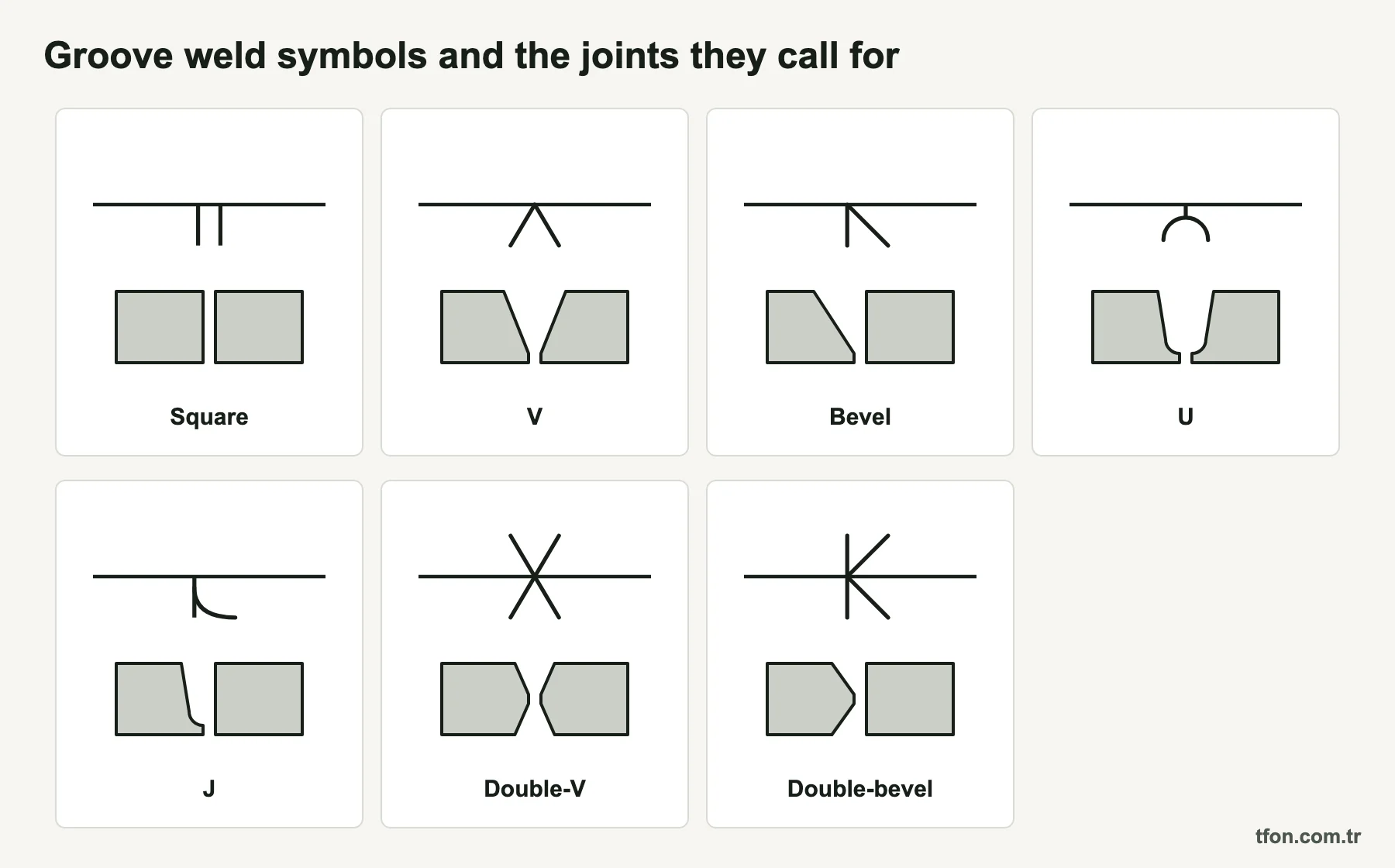
- Square groove: square edges, usually with a root opening; the weld relies on penetration through the material.
- V-groove: both members beveled. The angle at the symbol is the included angle, split equally between the plates on a symmetrical V.
- Bevel groove: one member beveled, the other square. Perpendicular leg on the left, arrow pointing to the beveled member.
- U and J grooves: a curved root and steep sidewalls save weld metal on thick plate. The U prepares both members, the J only one.
- Flare-V and flare-bevel: joints formed by curved surfaces, such as round bars, bent sheet edges or a tube on a plate.
A V on both sides of the line is a double-V groove, called an X-groove in European practice. A bevel on both sides is a double-bevel or K-groove, the usual full-penetration preparation for thick T-joints welded from both sides.
Bevel weld symbol: which plate gets the bevel
The bevel weld symbol looks the same whichever plate is meant, so the arrow carries that information. AWS A2.4 and ISO 2553 both point the arrow at the plate to be beveled, and AWS adds a break in the arrow line where the choice is not obvious.
Groove symbols found only in ISO 2553
ISO 2553 has separate Y and HY symbols for a single-V and a single-bevel with a broad root face. AWS shows the same joints with a V or bevel symbol and a depth of bevel smaller than the plate thickness. Typical angles and root faces for each groove are in the guide to weld bevel and groove types, and why weld beveling is necessary for thick plate welding explains when a groove is needed at all.
Groove Dimensions on the Symbol
On an AWS groove weld symbol, the depth of bevel S and the groove weld size (E) go to the left, the root opening goes inside the symbol, and the groove angle goes just outside it, further from the line. These values define the edge preparation and how deep the weld must penetrate.
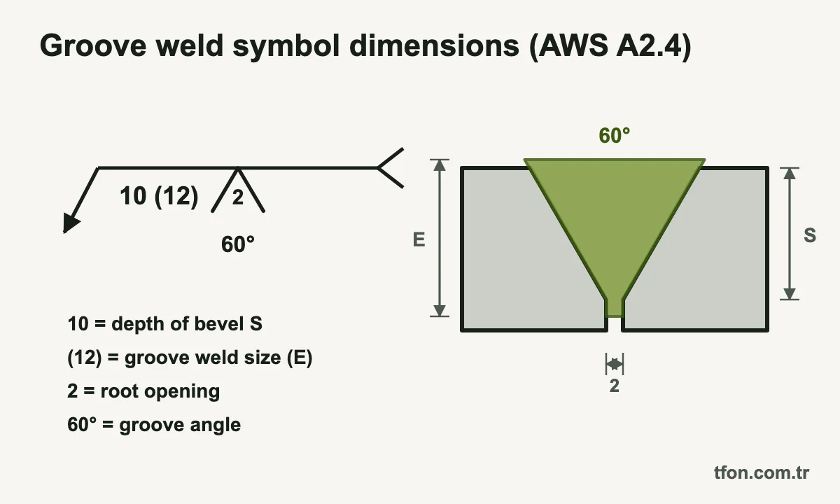
The table lists each dimension position on an AWS groove weld symbol and its meaning.
| Position | Value | Meaning |
|---|---|---|
| Left of the symbol | Depth of bevel S, such as 1/2 | Depth of the preparation from the plate surface |
| Left, in parentheses | Groove weld size (E), such as (3/8) | Penetration the finished weld must reach |
| Inside the symbol | Root opening, such as 1/8 | Gap between the members at the root after fit-up |
| Outside the root opening | Groove angle, such as 60° | Included angle; on a single-bevel groove it equals the bevel angle |
| Right of the symbol | Length or length-pitch | Weld length when less than the full joint |
| Nothing on the left | No S and no (E) | CJP on single and symmetrical double grooves |
AWS A2.4 has no separate position for the root face. On a single groove it is the plate thickness minus S: a 3/4 in plate with S = 1/2 leaves a 1/4 in root face.
CJP or PJP from the symbol
A single-groove or symmetrical double-groove symbol with no S and no (E) calls for complete joint penetration (CJP), and many drawings add CJP in the tail to remove doubt. When E is less than the plate thickness, the weld is a partial joint penetration (PJP) weld, and E is the value the designer counts on. How AWS D1.1 treats both cases is covered in complete vs partial joint penetration.
E is often smaller than S on narrow bevels, because the bottom of the preparation may not fuse fully. The code or the qualified WPS sets that relationship, not the symbol.
ISO 2553 and the angle check
ISO 2553 writes butt weld penetration as s, such as s8 for 8 mm, and implies full penetration when none is given. Groove angle and root gap appear at the symbol or come from a WPS or ISO 9692-1. Before setting a machine, check the angle: on a V or X groove, 60° means 30° per plate, while on a bevel groove the value belongs to the one prepared plate. The effect of the angle on penetration and distortion is covered in how bevel angle affects weld quality.
Supplementary Symbols: All Around, Field Weld, Melt-Through, Backing and Contour
Supplementary symbols add instructions the basic weld symbol cannot carry: where the weld runs, where it is made, and what the root and face must look like. Most have direct equivalents in ISO 2553.
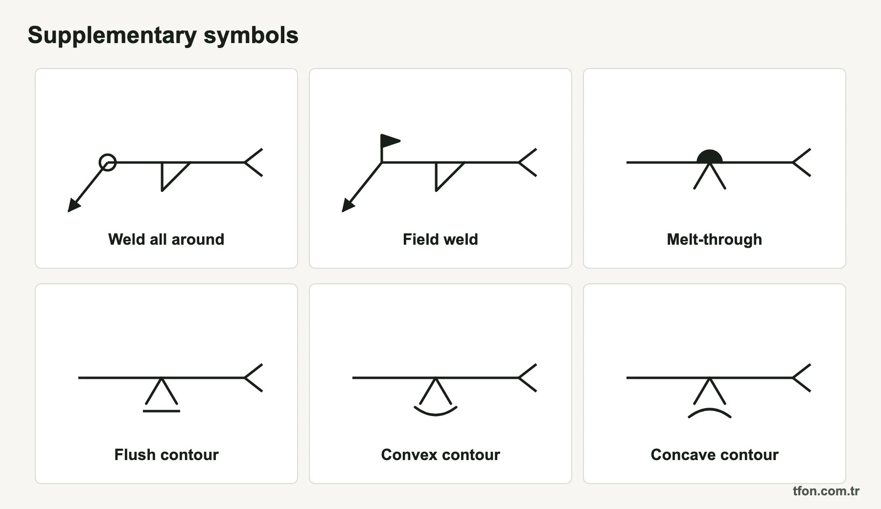
The table lists the common supplementary symbols of AWS A2.4, where each is drawn and what it requires.
| Symbol | Drawn as | Position | Meaning |
|---|---|---|---|
| Weld all around | Circle | Arrow junction | Weld continues around the whole joint |
| Field weld | Small flag | Arrow junction | Weld is made at the site, not in the shop |
| Melt-through | Half-circle | Opposite the weld symbol | Visible root reinforcement from a weld made from one side |
| Backing | Rectangle, R inside if removed | Opposite the groove symbol | Backing strip or bar on the root side |
| Contour | Straight line, outward arc or inward arc | Over the weld symbol | Flush, convex or concave weld face |
| Finishing letter | C, G, H, M or R | Outside the contour symbol | Chipping, grinding, hammering, machining or rolling |
Weld all around saves repeating a symbol on every side of a closed joint, such as a tube on a base plate. The field weld flag leaves the joint for the site, which affects fit-up, tacking and shipping. ISO 2553 uses both symbols and calls the field weld a site weld.
Melt-through and the back or backing weld use similar half-circles. Melt-through asks for visible root reinforcement from a one-sided weld, while a back weld is a separate root-side pass made after the groove weld and a backing weld one made before it; the tail or a multiple reference line says which. For backing strips, an R in the rectangle means remove after welding, and ISO 2553 uses M for permanent and MR for removable backing.
A contour symbol without a finishing letter must be achieved by welding alone; with G, for example, the face is ground to that contour. ISO 2553 adds a symbol for smoothly blended weld toes. The letter says how, not how smooth, so a roughness limit needs a surface texture symbol, as explained in the surface finish chart.
AWS A2.4 vs ISO 2553: Key Differences
AWS A2.4 and ISO 2553 share most basic weld symbols but differ in how they show the side, fillet size, intermittent spacing, backing and process. These differences matter most on export work, where a drawing made to one standard is welded or inspected by a shop trained on the other.
The table compares AWS A2.4 and ISO 2553 on the points that cause errors in the shop.
| Topic | AWS A2.4 | ISO 2553 |
|---|---|---|
| Reference line | Single solid line | System A: solid line plus dashed identification line. System B: single solid line |
| Arrow side | Symbol below the line | System A: symbol on the solid line, above or below. System B: below the line |
| Other side | Symbol above the line | System A: symbol on the dashed line. System B: above the line |
| Fillet size | Leg size, no prefix | Prefix a (throat) or z (leg) |
| Intermittent welds | Length-pitch, pitch center to center | n × l (e), e = space between segments |
| Groove penetration | S (E) left of the symbol | Prefix s left of the symbol, such as s8 |
| Groove with no dimensions | CJP on single and symmetrical double grooves | Full penetration implied |
| Broad root face | No separate symbol; shown through S | Separate Y and HY symbols |
| Backing strip | Rectangle; R inside means remove | M (permanent) or MR (removable) in a rectangle |
| Process in the tail | Letters such as SMAW, GMAW, FCAW, GTAW, SAW | ISO 4063 numbers such as 111, 135, 136, 141, 121 |
| Typical units | Inches, often fractions | Millimeters |
Tails differ too. An AWS tail holds the process, a WPS number or a note such as CJP, while ISO 2553 tails often list several items separated by slashes. A tail reading 135/ISO 5817-C/ISO 6947-PB calls for MAG welding with solid wire, quality level C and the horizontal-vertical position.
Two habits prevent most cross-standard errors. Confirm the standard and the system in the title block first, and write converted fillet sizes and spacing on the shop traveler instead of converting in your head at the welding station.
How to Read a Welding Symbol: Worked Examples
To read a welding symbol, start at the arrow, find the side, identify the weld symbol, read the dimensions left to right, then check the supplementary symbols and the tail. The figure shows four typical symbols next to the joints they produce, and the examples below walk through four readings.
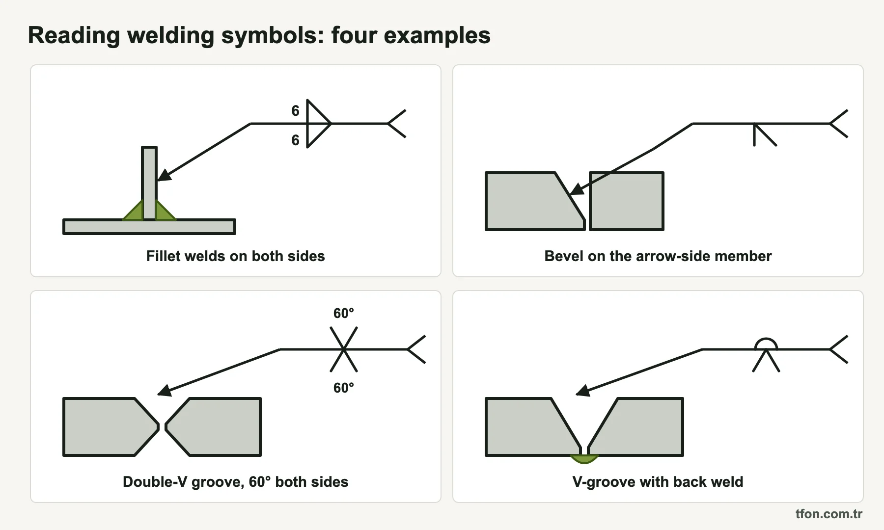
Example 1: double fillet on a T-joint (AWS A2.4)
A fillet triangle sits below and above the line, each with 5/16 on its left and nothing on its right. Reading: 5/16 in fillet welds on both sides of the stem, continuous over the full length of the joint.
Example 2: single-bevel PJP groove, field weld (AWS A2.4)
A bevel symbol sits below the line with 1/2 (3/8) on its left and 45° below it, a field weld flag sits at the junction, and the arrow breaks toward the left plate of a butt joint in 3/4 in plate. Reading: bevel the left plate on its arrow-side face, 1/2 in deep at 45°, leaving a 1/4 in root face, while the right plate stays square. Weld at the site to a groove weld size of 3/8 in, with the root opening taken from the WPS or a joint detail.
Example 3: V-groove CJP with backing (AWS A2.4)
A V symbol sits below the line with 1/4 inside it and 60° below it, a rectangle without an R sits above the line, and the tail reads GMAW. Reading: arrow-side V-groove, 60° included angle (30° per plate), 1/4 in root opening, complete joint penetration by gas metal arc welding onto backing that stays in place.
Example 4: intermittent fillet on the other side (ISO 2553 system A)
A fillet symbol hangs from a dashed line drawn below the continuous line, with a4 on its left, 3 × 100 (150) on its right and 135 in the tail. Reading: other-side fillet, 4 mm throat (leg about 5.7 mm), three 100 mm segments with 150 mm gaps covering 600 mm, MAG welded with solid wire. An AWS reader who sees a symbol below the line would weld the wrong face.
From Groove Symbol to Edge Preparation
A groove weld symbol is also a cutting instruction: it tells the shop which plate to bevel, on which face, to what angle and depth, and which edge stays square. A wrong bevel often shows up only at fit-up, so the symbol must be read before the plate reaches the beveling station.
- Member: for bevel and J grooves, the arrow or its break names the plate. V and U grooves prepare both plates.
- Face: an arrow-side symbol means the groove opens toward the arrow side, an other-side symbol means the opposite face, and symbols on both sides mean both faces.
- Angle: a bevel groove angle is the bevel angle of that plate. A V-groove angle is split between the plates.
- Depth and root face: S sets the cut depth, and the land left below it is the root face.
- Root opening: set at fit-up, not at beveling.
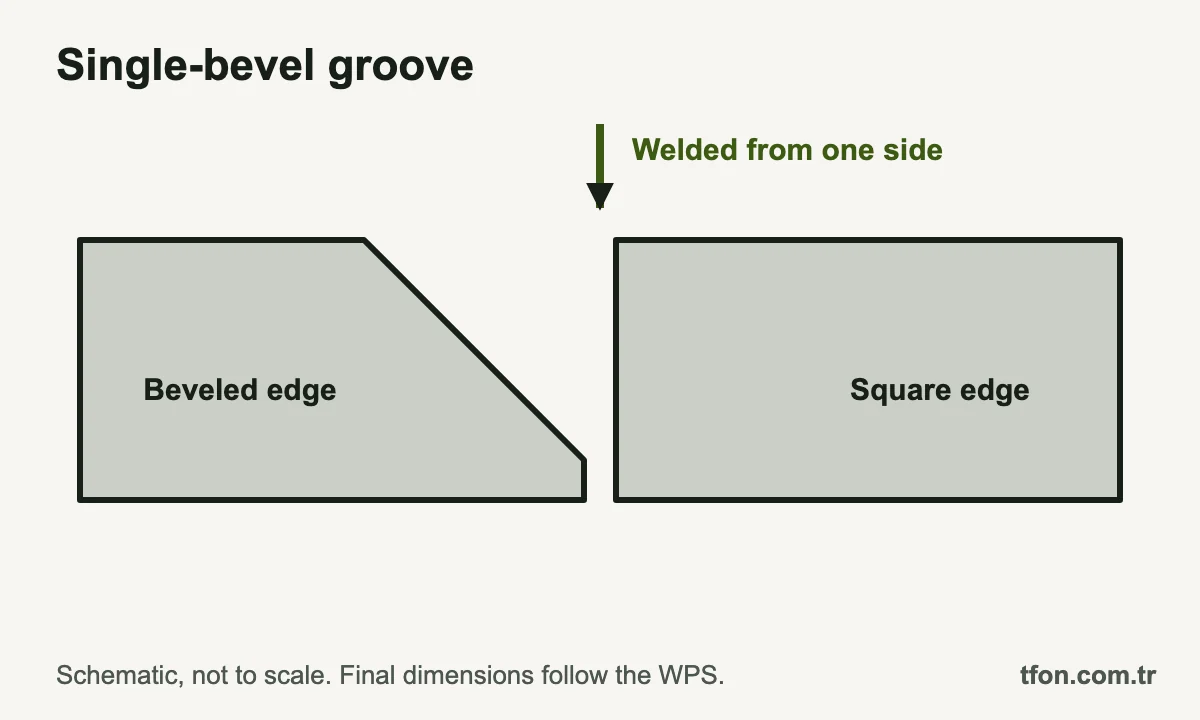
A single-bevel symbol becomes this preparation: one plate beveled, its mate left square. A double-bevel symbol asks for the same cut on both faces of one plate, which is typical for thick T-joints welded from both sides.
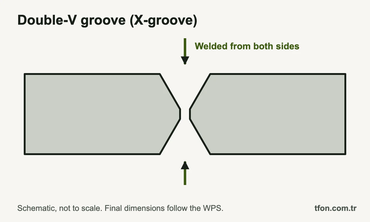
A V on both sides of the line becomes a double-V or X preparation: both plates beveled on both faces around a central root face. Each cut must hold its angle and root face along the whole edge, which is hard to achieve by hand grinding on long plates.
Beveling to the symbol with a plate beveling machine
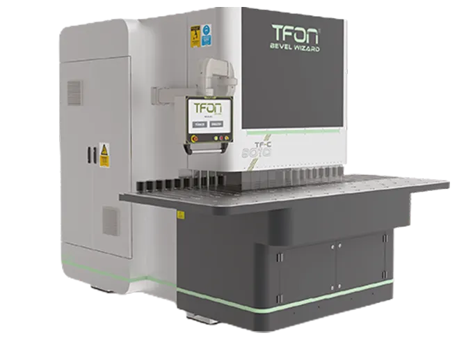
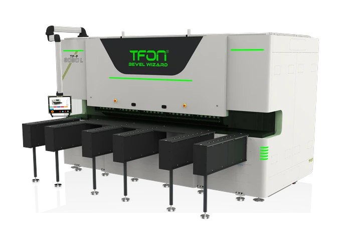
Straight-faced preparations such as single-bevel, V, Y, double-V and double-bevel grooves are angle and depth settings on a plate beveling machine. TFON Bevel Wizard machines bevel plate and sheet 4 to 100 mm thick at a working angle of -30° to +80°. The Bevel Wizard TF-C 8010 L has a sliding table for parts up to 12,000 mm long, and the Bevel Wizard TF-F 8030 L has a fixed table for parts 60 to 3,000 mm long.
J and U grooves need a root radius and are usually machined. Before production, match the angle reference of the machine to the drawing and check the first edge with a bevel gauge. Thermally cut edges should be free of slag and oxide before beveling, as described on the page on plasma and oxy-fuel cut parts.
TFON Machines for This Job
-
TFON Bevel Wizard® TF-C 8010 L
Plate beveling machine for 4 to 100 mm plate, parts up to 12,000 mm long, working angle -30° to +80°
Specifications Request a Quote -
TFON Bevel Wizard® TF-F 8030 L
Plate beveling machine for small and mid-size parts, 60 to 3,000 mm long, 4 to 100 mm thick
Specifications Request a Quote
Frequently Asked Questions
How do you read a welding symbol?
Start at the arrow, then check whether the weld symbol is below the reference line (arrow side) or above it (other side). Identify the weld type from the symbol, read the cross-section dimensions on its left and the length or pitch on its right, then check the supplementary symbols and the tail.
What does it mean when the weld symbol is below the line?
In AWS A2.4 and ISO 2553 system B, a weld symbol below the reference line means the weld goes on the arrow side, the side the arrow touches. A symbol above the line means the other side. In ISO 2553 system A, the line the symbol touches, solid or dashed, decides the side instead.
What is the dashed line on a welding symbol?
It is the identification line of ISO 2553 system A. A symbol on the solid line applies to the arrow side and a symbol on the dashed line to the other side, whether the dashed line is drawn above or below. It is omitted for symmetrical welds.
What do the numbers on a fillet weld symbol mean?
The number on the left is the weld size, and the numbers on the right give the length and, for intermittent welds, the spacing. AWS A2.4 gives the leg size and a center-to-center pitch, such as 2-6. ISO 2553 prefixes the size with a (throat) or z (leg) and writes intermittent welds as n × l (e).
What is the difference between a bevel weld symbol and a V-groove weld symbol?
A bevel weld symbol means only one member is beveled, while a V symbol means both members are. With a bevel symbol, the arrow points at the plate to prepare, with a break where the choice is not obvious.
What do the flag and the circle on a welding symbol mean?
The flag at the arrow junction means field weld: the weld is made at the site rather than in the shop. The circle at the same point means weld all around the joint. Both symbols are used in AWS A2.4 and ISO 2553.
What does a groove weld symbol with no dimensions mean?
Under AWS A2.4, a single or symmetrical double groove symbol with no depth of bevel and no weld size calls for complete joint penetration. ISO 2553 also implies full penetration when no depth is given. A partial penetration weld needs its depth and weld size on the symbol.
Is there a welding symbols chart PDF?
Yes. The welding symbols chart on this page is available as a free one-page PDF for printing. It is a reading aid and does not replace the standard.
Let Us Review Your Part
Share the material, cutting method, part dimensions and the next operation, with photos of both faces. We will recommend the machine and station sequence that fits the part.