


Knowledge Base
What Is a Burr and How Does It Form on Sheet Metal?
A burr is a raised edge or small piece of material that stays attached to a part after cutting, punching, shearing or machining. It forms when metal deforms or refreezes at the edge instead of separating cleanly. On sheet metal parts, the burr usually sits on the exit side of the cut.
TFON Machines for This Job
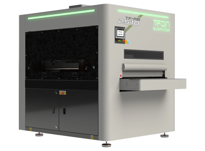
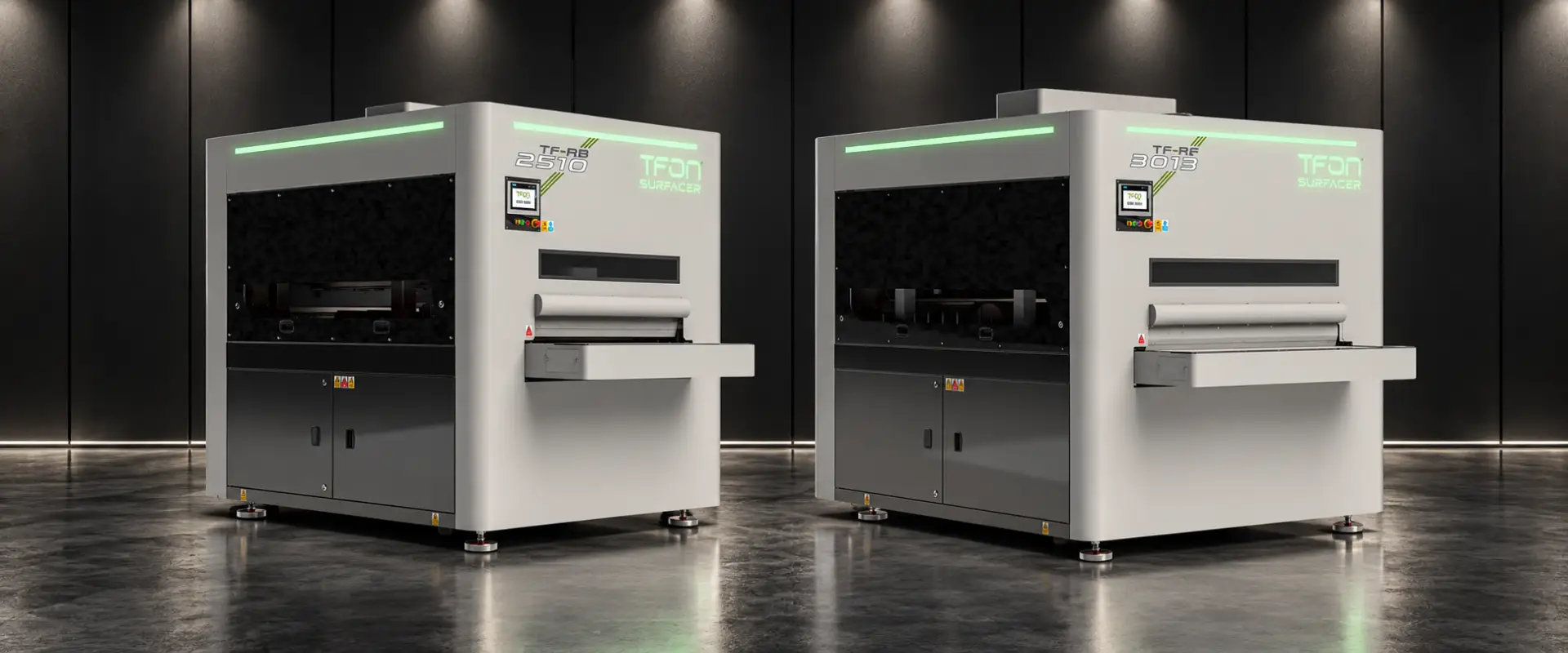
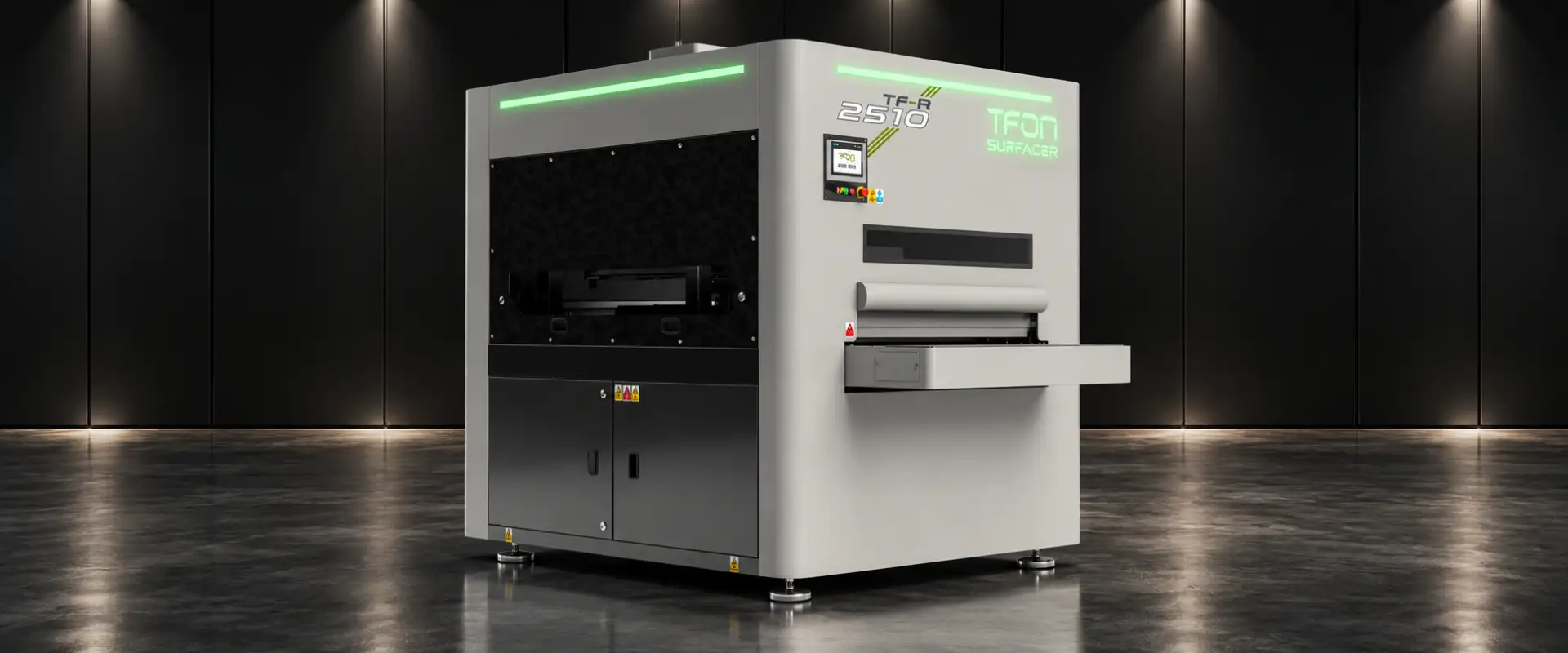
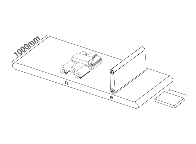
- TFON Surfacer® TF-RB-2510 1,000 mm working width; abrasive belt deburring and edge rounding on one face in a single pass Specifications Request a Quote
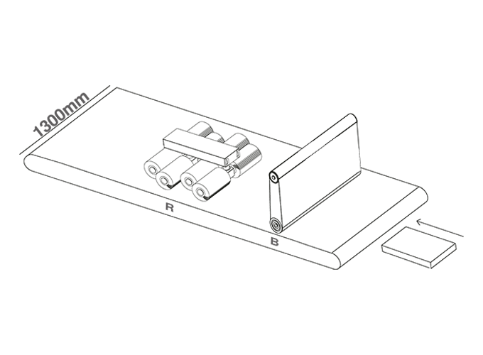
- TFON Surfacer® TF-RB-3013 1,300 mm working width, parts up to 600 kg; abrasive belt deburring and edge rounding in one frame Specifications Request a Quote
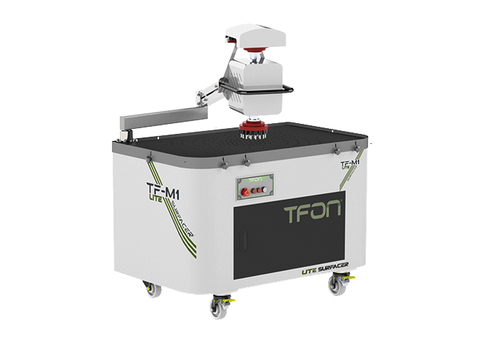
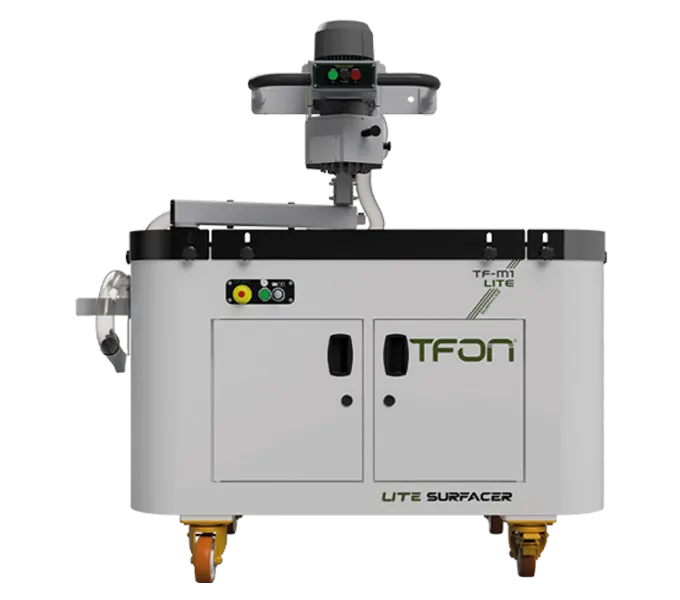
- TFON Lite Surfacer® TF-M1 LITE H1 Manual single-head deburring machine for 3 to 200 mm parts on an 800 x 1300 mm vacuum table Specifications Request a Quote
What Does Burr Mean in Metalworking?
A burr is material that sticks out past the intended edge of a part after it has been cut, punched, sheared, drilled or machined. It stays attached to the part. It can be a continuous lip along a sheared edge, a thin fin at a hole exit or a small bead of refrozen metal under a laser cut.
Technical drawings treat a burr as a deviation from the ideal edge. ISO 13715, the standard for indicating edges of undefined shape, distinguishes an overhang of material on an external edge (a burr) from a material deficit (an undercut) and gives a symbol that states how much of either is allowed. A drawing that says "deburr all edges" without a value leaves the acceptance level open, which is why many disputes over burrs start on the drawing, not on the shop floor.
The word causes some confusion in searches. A "burr" or "bur" is also a rotary cutting tool, usually carbide, used in a die grinder to shape or deburr metal. This guide covers the edge defect. When people ask what deburring is, they mean removing that defect.
Three edge conditions are often mixed up with burrs:
- Sharp edge: a clean corner with no projecting material. It can still cut a hand or thin a paint film. Treating it is edge rounding, not deburring.
- Slag or dross: resolidified melt from plasma, oxy-fuel or laser cutting. It behaves differently from a burr; see slag vs dross.
- Oxide layer: the dark scale left on laser cut faces when oxygen is the assist gas. It is a surface condition, not a projection.
How Burrs Form in Punching and Shearing
A punched or sheared edge shows the whole cutting sequence if you look at it under a magnifier. On the side where the punch entered, the edge is slightly rounded; this is the rollover or die roll. Below it is a smooth, shiny band, the burnish zone, where the metal was sheared. Below that is a rougher fracture zone where the material cracked through. The burr sits at the end of the fracture zone, on the die side.
The burr forms because metal does not separate cleanly at the tool edge. It stretches and flows until the cracks from the punch and the die meet. Anything that delays or misaligns those cracks leaves more material hanging on the exit edge.
Clearance
Punch-to-die clearance is usually specified per side as a percentage of material thickness, and tooling suppliers publish recommended values by material type and thickness. Too much clearance produces more rollover and a taller burr. Too little clearance produces a second burnish band, higher punching force and faster tool wear. The same logic applies to the blade gap on a shear.
Tool wear
A dull punch or die edge pushes metal instead of cutting it, so burr height grows as tooling wears. Tracking burr height on a sample part at fixed intervals is one of the simplest ways to schedule tool sharpening.
Material
Ductile materials such as soft aluminum, copper and low-carbon or stainless sheet tend to form larger burrs than harder, less ductile grades, because they stretch further before fracturing.
Punched parts also carry the burr on a predictable side. That matters downstream: in bending, the usual rule is to put the burr side on the inside of the bend so the fracture zone is not stretched, and on a deburring machine it tells you which face to feed toward the processing stations.
How Burrs Form in Laser, Plasma and Machining
Thermal cutting does not shear metal. It melts or burns a kerf and blows the melt out with gas. A burr on a laser or plasma part is therefore mostly molten metal that refroze on the exit edge before the gas could clear it.
Laser with nitrogen or air. Stainless steel, aluminum and increasingly mild steel are cut with nitrogen or compressed air to get an oxide-free edge. When gas pressure, focus position or speed drift, a fine bead hangs on the bottom edge. It is small but sharp and often continuous around every contour, including internal holes.
Laser with oxygen. Oxygen cutting of mild steel puts an oxide layer on the cut face and, when settings drift, a bead on the bottom edge, mostly on thicker plate. The guide on oxygen vs nitrogen laser cutting covers when that layer causes coating problems.
Microjoints and pierce points. Nested laser and punch parts are held in the skeleton by small tabs. When the part is broken out, each tab leaves a small nub on the edge. Pierce points can leave a crater and spatter on the top face.
Plasma and oxy-fuel. The bottom-edge residue ranges from a light bead to heavy slag, depending on cut speed, torch height and consumables.
Drilling, milling and tapping. Drills push a crown-shaped burr out at the hole exit. Milling cutters leave burrs where the tool leaves the workpiece. Thread starts carry a small burr.
| Cutting method | Where the burr sits | Typical form | Main drivers |
|---|---|---|---|
| Punching and blanking | Die side (exit side of the punch) | Continuous lip along the fracture zone | Punch-to-die clearance, tool sharpness, material ductility |
| Shearing | Bottom edge on the side that faced the lower blade | Lip along the whole cut length | Blade gap for the thickness, blade wear |
| Fiber or CO2 laser, nitrogen or air | Bottom edge (beam exit) | Fine bead of resolidified metal, sometimes called laser dross | Focus position, gas pressure, nozzle condition, speed |
| Laser with oxygen | Bottom edge; oxide on the cut face | Small bead, mostly on thicker plate | Oxygen purity and pressure, speed, plate surface |
| Plasma and oxy-fuel | Bottom edge | Dross or slag, from light bead to heavy deposit | Speed, torch height, consumables, gas |
| Drilling, milling, tapping | Hole exit, edges of milled faces, thread starts | Crown or rollover burr | Tool geometry and wear, feed, exit support |
A single deburring method therefore rarely covers a mixed production: a punched part has a ductile lip on one face, a fiber laser part a fine bead around every contour. The application page for laser cut and punched parts shows how those differences affect the processing route.
Types of Burrs
Manufacturing engineering handbooks classify burrs by how they form. The classification is useful on the shop floor because each type points to a different cause and a different fix.
| Burr type | How it forms | Where you see it on sheet parts | What usually removes it |
|---|---|---|---|
| Rollover burr | Material bends over at the exit instead of shearing off; the most common type | Punched and sheared edges, drilled hole exits | Abrasive belt, then brush for the edge |
| Poisson burr | Material bulges sideways when a tool compresses it | Edges next to heavily loaded tool contact, stamped features | Belt or brush, depending on size |
| Tear burr | Material tears loose rather than shearing cleanly | Worn tooling, ductile alloys, blanked contours | Belt; check tooling first |
| Cut-off or breakout burr | A projection left where the part separates from the stock | Microjoint tabs on laser and punch nests, parted blanks | Belt, file or tab grinding |
| Recast bead (laser or plasma burr) | Molten metal refreezes on the exit edge | Bottom edge of thermally cut parts | Belt for light beads; heavy removal stage for dross |
Two practical points follow from the table. First, the type tells you whether to fix the cutting side. A growing rollover or tear burr on punched parts usually means worn tools or wrong clearance, and sharpening costs less than extra deburring. A recast bead on fiber laser parts usually means a gas or focus setting, and a cut test costs less than grinding every edge.
Second, the type sets the removal method. A rollover burr on sheet is thin and ductile, and an abrasive belt removes it quickly. A cut-off burr at a microjoint is a short, stiff nub that a belt handles but a soft brush may only polish. A heavy recast bead from plasma behaves like slag and needs a breaking stage first.
Burr height alone does not describe the problem. A small burr on a hole edge in a hydraulic manifold plate can be more critical than a larger burr on the outside edge of a bracket that goes into a weldment. Record the type, the location and the height together.
Why Do Burrs Have to Be Removed?
Burrs cost money twice: once when they injure, jam or reject something downstream, and again when someone has to remove them by hand at the last minute. The reasons to deburr fall into five groups.
- Operator safety. Burrs and sharp edges cause cuts during handling, stacking, bending and assembly. Gloves reduce the risk but do not remove it, and cut-resistant gloves slow down fine work.
- Coating quality. Liquid paint and powder coating pull away from sharp edges as they cure, so the film is thinnest exactly where a burr or sharp corner sits. Corrosion on painted parts often starts at edges for that reason. Removing the burr and giving the edge a small radius lets the coating build a more even film.
- Assembly and fit. A burr on a mating face stops parts from sitting flat, throws off hole alignment and can prevent fasteners from seating. In electrical enclosures, burrs at cut-outs and holes can damage cable insulation.
- Forming. A burr on the outside of a bend puts the fracture zone under tension and increases the risk of cracking. Burrs also mark press brake tooling and change the bend line position on backgauge contact.
- Welding. Burrs and dross change the root gap and the root face along a joint. ISO 9692-1, the joint preparation standard for steels, notes that the edges of the root face should be deburred.
There is also a measurement reason. A burr adds to the measured size of a part, and a part that fails inspection because of a burr is often dimensionally correct underneath it.
Not every edge needs the same treatment. An internal edge that no one touches, which is welded over or which sits inside an assembly may only need the burr taken off. An edge that will be painted, handled daily or touched by a customer may need a defined radius as well. Writing that difference on the drawing, instead of "deburr all edges", keeps both cost and disputes down.
How Is Burr Height Measured?
Burr height is the distance the burr projects beyond the surface it grew from. On sheet metal it is usually measured perpendicular to the face on the exit side of the cut. Some specifications also limit burr thickness at the root, because a thin tall burr and a thick short one behave differently in assembly.
| Method | What it tells you | Good for | Limits |
|---|---|---|---|
| Fingernail, cloth or cotton swab | Burr present or not | Quick shop floor check | No number; depends on the person |
| Caliper or micrometer | Thickness over the burr minus sheet thickness | Straight edges on sheet | Anvils can flatten a soft burr; light force only |
| Dial indicator or height gauge on a surface plate | Height of the burr above the face | Repeatable checks on flat parts | Part must lie flat; slow on long contours |
| Magnifier with reticle or measuring microscope | Burr height and shape at a point | Small features, holes, audit samples | Few points per part |
| Stylus or laser profile measurement | Edge profile including burr and radius | Process capability studies, trials | Equipment and time; lab rather than line |
Set up a sampling plan
- Measure at defined positions: a straight edge, an outside corner, an inside corner, a small hole and a microjoint location.
- Check both faces. A part can be clean on the face you look at and carry a burr on the other one.
- Measure incoming parts as well as finished parts. The difference shows how much work the deburring step is really doing and whether the cutting side is drifting.
- Record tool changes, laser settings or cutting table used, so a trend can be traced back to its cause.
Write the limit on the drawing
ISO 13715 lets the designer state the permitted burr on an external edge as a plus value next to the edge symbol, and a required undercut as a minus value. Some drawings use a visual criterion instead, such as no burr visible at a stated magnification. Either works if it is written down and matched with a measuring method the shop can apply on every batch.
A burr limit on its own does not define the edge. If the edge also needs a radius for coating or handling, specify it separately and measure it separately.
Burr, Sharp Edge, Slag or Oxide: Name the Edge Condition First
Choosing a deburring method starts with naming the edge condition correctly, because each condition matches a different station on a deburring machine or a different hand tool. On TFON Surfacer machines, the model code shows which conditions a machine is built to treat.
- Burr: removed by an abrasive belt station (B in the TFON model code). The belt cuts the projection flush with the face.
- Sharp edge: rounded by flap wheel or brush stations (R). These flexible tools also reach the edges of holes and internal cut-outs that a flat belt does not touch.
- Heavy slag or dross: broken off by a heavy deburring station (C) before the belt.
- Oxide on the cut face: removed by brush stations for laser oxide removal.
- Surface finish: a satin finish station (F) gives the face a uniform grain after deburring.
For punched and fiber laser parts where the job is burr removal plus a rounded edge, the TF-RB-2510 (1,000 mm working width) and the TF-RB-3013 (1,300 mm working width) combine an abrasive belt with edge rounding stations in one frame. Both have a conveyor speed of 0.6 to 4.0 m/min and vacuum and/or magnetic part holding, and both treat one face per pass. The full range is on the deburring and edge rounding machines page.
Once the condition is named, the next question is method and volume. The guide How to Deburr Sheet Metal compares hand, vibratory, belt and brush methods, and deburring tool vs deburring machine helps decide when hand tools stop being economical.
TFON Machines for This Job
-
TFON Surfacer® TF-RB-2510
1,000 mm working width; abrasive belt deburring and edge rounding on one face in a single pass
Specifications Request a Quote -
TFON Surfacer® TF-RB-3013
1,300 mm working width, parts up to 600 kg; abrasive belt deburring and edge rounding in one frame
Specifications Request a Quote -
TFON Lite Surfacer® TF-M1 LITE H1
Manual single-head deburring machine for 3 to 200 mm parts on an 800 x 1300 mm vacuum table
Specifications Request a Quote
Frequently Asked Questions
Is a burr the same as a bur?
In metalworking both spellings name two different things. A burr on a part is the unwanted projection left by cutting or machining. A burr or bur used as a tool is a rotary cutter, usually carbide, that runs in a die grinder. The tool can remove the defect, which adds to the confusion.
Which side of a punched part has the burr?
The burr forms on the die side, which is the side where the punch exits the material. The punch entry side shows the rounded rollover. Knowing this lets you orient parts consistently in bending, where the burr side usually goes on the inside of the bend, and in deburring.
Can burrs be avoided completely?
Rarely. Correct clearance, sharp tools and tuned laser or plasma settings keep burrs small, but some burr or sharp edge remains on most cut parts. The practical goal is a burr small and consistent enough that one defined finishing step brings every part within the drawing limit.
Are laser cut parts burr-free?
Not always. Laser cutting with nitrogen or air can leave a fine bead of refrozen metal on the bottom edge, and microjoints leave small nubs where parts were held in the sheet. Oxygen cutting adds an oxide layer on the cut face. How much remains depends on the settings and the material.
How big can a burr be before it must be removed?
There is no single number. The drawing or customer specification sets the limit, for example with an ISO 13715 edge symbol or a visual criterion. Handling safety, coating, assembly and welding each set different requirements, so the same burr can be acceptable on one edge and rejected on another.
Let Us Review Your Part
Share the material, cutting method, part dimensions and the next operation, with photos of both faces. We will recommend the machine and station sequence that fits the part.