


Knowledge Base
How to Deburr Sheet Metal: Methods Compared
Deburring sheet metal means removing the burrs that cutting and punching leave on part edges, and usually giving those edges a defined condition. The method depends on part size, volume and the edge the next operation needs: hand tools, grinders, vibratory finishing, or belt and brush deburring machines.
TFON Machines for This Job
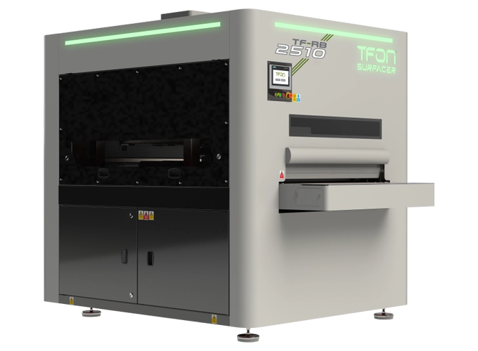
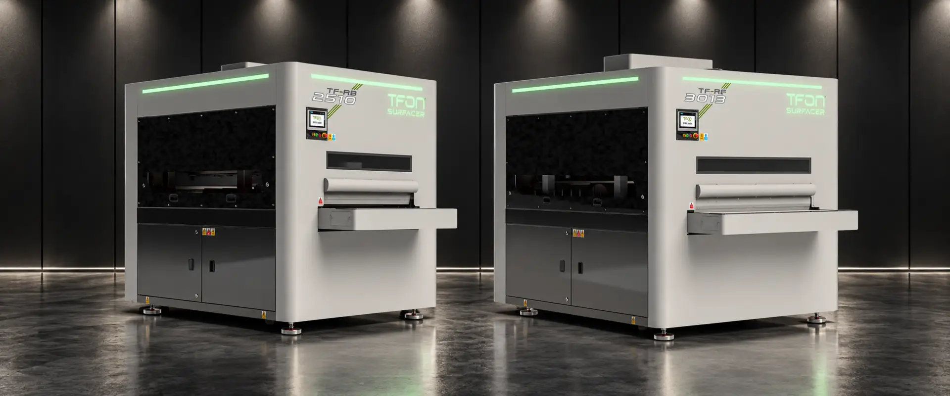
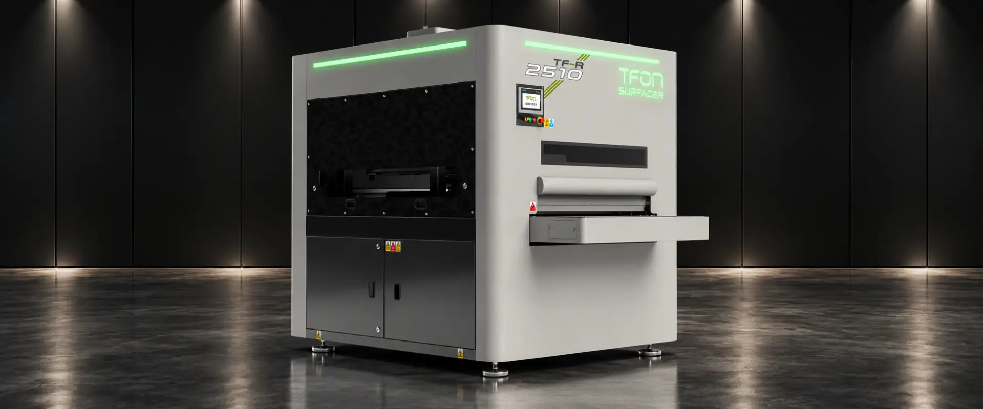
- TFON Surfacer® TF-RB-3013 1,300 mm working width; abrasive belt deburring and edge rounding on one face in a single pass Specifications Request a Quote
- TFON Surfacer® TF-R-3013 1,300 mm working width; edge rounding and oxide removal with eight Ø350 mm flap wheels Specifications Request a Quote
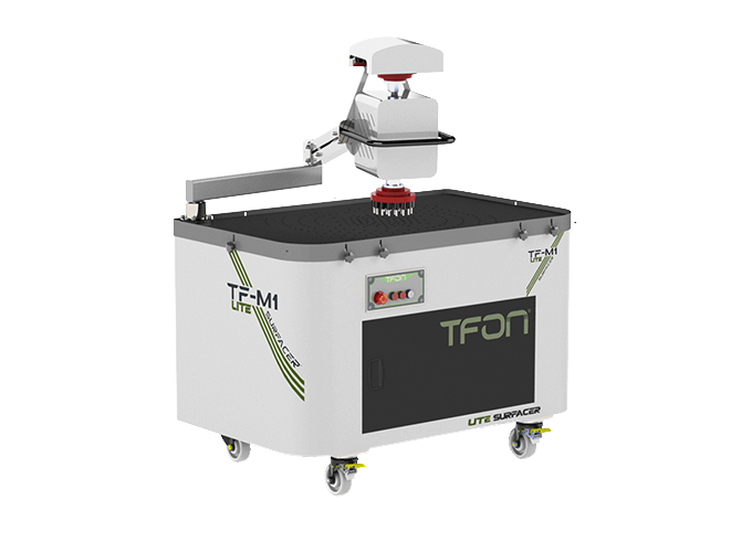
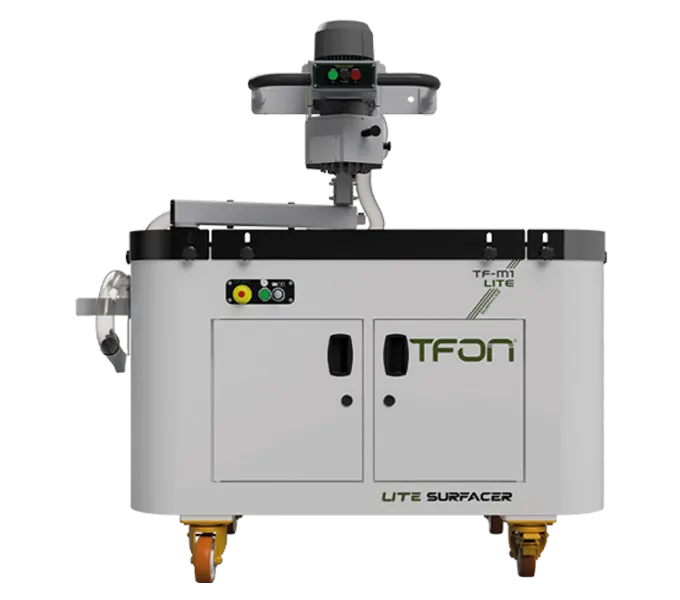
- TFON Lite Surfacer® TF-M1 LITE H1 Manual single-head deburring machine for 3 to 200 mm parts on an 800 x 1300 mm vacuum table Specifications Request a Quote
How to Reduce Burrs in Sheet Metal Before You Deburr
The cheapest burr is the one that never forms. Before comparing deburring methods, check whether the cutting side is producing avoidable work. A small, consistent burr lets one finishing step handle every part; a large, variable burr forces extra passes, coarser abrasives and hand rework.
- Punching and shearing: keep punch-to-die clearance and shear blade gap within the tooling supplier's values for the material and thickness. Sharpen on a schedule based on measured burr height, not on visible damage. Check tool alignment after each changeover.
- Fiber and CO2 laser: verify focus position, assist gas pressure and purity, nozzle condition and centering, and cut speed. A bottom-edge bead that appears on one machine and not another usually points to optics or gas, not to the part program.
- Microjoints: use as few tabs as the nest allows, keep them small, and place them on edges that are easy to reach or not critical to fit.
- Plasma and oxy-fuel: run inside the cut chart, replace worn consumables and keep torch height control working. The guide on slag vs dross covers the causes in detail.
- Drawings: state the edge requirement per edge. "Burr-free, R 0.5 on the painted face" is something a shop can produce and inspect. "Break all sharp edges" is not.
None of these steps removes burrs completely. They shrink the job that deburring has to do and make it predictable, which matters more to cost than the choice between two finishing methods.
Hand Deburring: Files, Scrapers, Edge Tools and Grinders
Hand deburring is still how most shops start, and for single parts and prototypes it is often the right answer. The common deburring tools for sheet metal are:
- Swivel blade deburring tools: a hooked blade in a rotating holder, pulled along the edge. Fast on straight edges and hole rims of thin sheet.
- Double-blade sheet edge tools: two blades at an angle that take a small chamfer off both corners of a sheet edge in one stroke.
- Files and scrapers: slower, but controllable on heavier burrs and short edges.
- Countersinks: in a hand holder or a drill, for hole edges.
- Abrasives: sandpaper on a block or non-woven hand pads for light burrs and edge breaks on thin sheet.
- Angle grinders and die grinders: flap discs, non-woven wheels or carbide burrs for heavy plate, dross and weld prep.
Technique matters more than the tool. Work in one direction along the edge, keep the tool at a constant angle, and stop once the burr is gone. On thin sheet, extra strokes create a visible chamfer and can change hole sizes. On stainless steel, use tools and abrasives that have not touched carbon steel, because embedded iron particles rust later. The article on deburring stainless steel without damaging the surface explains why.
The limits appear with volume. Hand results vary between operators and between the first and last part of a shift, the underside of the part is easy to forget, and every edge is handled twice. Grinders add vibration exposure, noise and dust. Once the same parts come back every week, compare the hand deburring time per part against a machine; the guide on deburring tool vs deburring machine walks through that comparison.
Vibratory and Tumble Deburring
Vibratory finishing puts a batch of parts into a bowl or tub with abrasive media, water and a compound. The vibrating container keeps parts and media rubbing against each other, which removes burrs and rounds every exposed edge. Barrel tumbling does the same in a rotating drum, generally more slowly.
The method is strong on small parts in large quantities: stamped clips, turned components, small brackets. It treats all edges and both faces in one cycle and gives an even radius. It also changes the faces of the part, so it is less suitable where a surface must stay untouched or needs a directional grain.
Sheet metal parts bring specific limits. Thin flat parts can stick together in the wet process, large panels do not fit or bend, media can lodge in small holes and slots, and parts can mark each other. The process needs water and compound handling, and carbon steel parts need drying or rust protection afterward.
TFON does not build vibratory or tumble finishing machines. The guide on vibratory vs belt and brush deburring compares the two approaches in detail, including when a shop uses both.
Belt Deburring Machines
A belt deburring machine feeds flat parts on a conveyor under a wide abrasive belt running around a contact drum. The belt cuts the burr flush with the face. Part holding keeps small parts from being pulled along by the belt: magnetic tables hold ferromagnetic steel, and vacuum tables also hold non-magnetic materials such as aluminum and austenitic stainless steel.
Belt deburring is efficient on straight edges and outside contours, and the result is repeatable once thickness, conveyor speed and belt setting are stored for the part. A flat belt, however, contacts the upper face and the edges it passes over. It does not reach into holes and cut-outs, and it cuts the face along with the burr, so grit selection matters on cosmetic parts.
Belt choice follows the job. Coarse grits in ceramic or zirconia-type grains remove heavy burrs; finer grits and non-woven belts give a cleaner face. TFON supplies aluminum oxide, zirconium and ceramic belts in grits 40 to 400, Cubitron belts in grits 24 to 400 and Scotch non-woven belts in coarse to very fine grades, in widths that match its machines. The abrasive belts page lists the sizes.
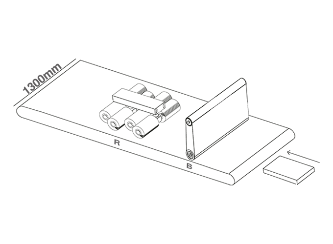
On TFON Surfacer machines the belt is the B station. In the TF-RB-3013 it is followed by edge rounding stations, so burr removal and edge rounding happen in one pass on one face. The machine takes parts up to 1,300 mm wide at a conveyor speed of 0.6 to 4.0 m/min; the second face needs a second pass.
Brush and Flap Wheel Deburring
Brush and flap wheel stations use flexible tools instead of a rigid belt. Abrasive flaps or filaments rotate against the part, follow the contour and reach into holes, slots and internal cut-outs. That makes them the tool for edge rounding: they give outside and inside edges a controlled radius, which is what paint and powder coating need to build an even film at the edge.
Brushes are gentler on the face than a belt, but they remove heavy burrs slowly. For that reason most production machines combine the two, belt first for the burr, brushes second for the edge. Wire brushes of the right type also take the oxide layer off laser cut edges.
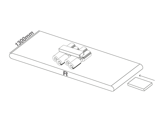
Edge radius depends on grit, the number of stations, rotation speed, brush pressure and conveyor speed. It also depends on part orientation, because brushes treat the edges of the face they work on. On TFON Surfacer machines the edge rounding stations (R) carry flap wheels of Ø300 x 400 mm on the 2510 series and Ø350 x 490 mm on the 3013 series, with a published flap wheel speed of 300/960 rpm. TFON edge rounding brushes come in grits 60 to 400, with a service life of up to 1,500 hours depending on use.
For parts that only need rounded, oxide-free edges and no belt, the TF-R-3013 uses edge rounding stations only. The landing page on the brush deburring machine explains when brush-only processing is enough, and edge rounding covers how to specify the radius.
Thermal and Electrochemical Deburring
Two further methods appear in most deburring overviews, although they are rarely used on flat sheet metal parts.
Thermal deburring, also called the thermal energy method, places parts in a closed chamber filled with a combustible gas mixture. Ignition produces a short burst of heat that burns off thin burrs, because a burr has little mass compared with the part. It reaches internal intersecting holes that no tool can touch, which is why it is used on hydraulic and fuel system components.
Electrochemical deburring dissolves burrs at defined locations with an electrode and electrolyte. Each part needs its own tooling, so it suits high volumes of identical machined parts.
Thermal deburring leaves a thin oxide film that usually has to be cleaned off, and electrochemical deburring needs electrolyte handling and part-specific fixtures. Both methods are specialized, and neither is part of the TFON range. TFON machines work mechanically, with belts, brushes, flap wheels and discs on flat cut parts, where these two methods are rarely the economic choice.
Deburring Methods Compared
No method wins on every part. The comparison below uses the criteria a production manager usually weighs: part size, volume, the edge result the next operation needs, how repeatable the result is and what the operator is exposed to.
| Method | Part size | Volume | Edge result | Repeatability | Operator exposure |
|---|---|---|---|---|---|
| Files, scrapers, swivel blades | Any; good for small features | Prototypes, single parts | Burr removed; edge break depends on skill | Low | Cuts, repetitive hand work |
| Angle grinder with flap or non-woven disc | Medium to large, heavy plate | Low to medium | Fast removal; risk of gouges and uneven chamfer | Low | Vibration, noise, dust, sparks |
| Vibratory or tumble finishing | Small loose parts that fit the tub | High, in batches | Even radius on all edges; faces also change | High within a batch | Low at the machine; wet handling |
| Through-feed belt machine | Flat parts, from small (holding permitting) to wide sheet | Medium to high | Burr cut flush on the processed face | High | Low; loading and unloading |
| Through-feed brush or flap wheel machine | Flat parts with holes and cut-outs | Medium to high | Rounded edges, including internal contours | High | Low; loading and unloading |
| Manual deburring machine | Parts that fit the table | Low to medium, mixed jobs | Depends on the operator | Medium | Moderate; operator guides the part |
| Thermal or electrochemical | Small machined parts, internal intersections | High | Internal burrs removed | High | Specialized cells; outside TFON scope |
Read the table by row and by column. A method that scores well on repeatability but cannot take the part size, or one that suits the volume but changes a face that must stay untouched, drops out regardless of its other strengths.
Which Deburring Method Fits Which Part?
Turned into decisions for typical sheet metal jobs, the comparison looks like this:
| Part or situation | First choice | Watch out for |
|---|---|---|
| Punched or laser cut steel brackets, 1 to 3 mm, painted later | Belt deburring plus edge rounding in one pass | Burr side orientation; second pass if both faces need an edge radius |
| Laser cut stainless panels with a visible face | Belt and brush machine with stainless-only consumables, satin finish station if the face needs a grain | Contamination from carbon steel abrasives; scratches on the visible face |
| Plasma or oxy-fuel cut plate with dross | Heavy slag station, then belt and brush | Slag roots at corners; part weight and holding |
| Large volumes of small turned or stamped parts | Vibratory finishing | Parts sticking together; media lodging in holes |
| Prototypes, rework, constantly changing jobs | Hand tools or a manual deburring machine | Consistency between operators |
| Cross holes in machined hydraulic blocks | Thermal or electrochemical deburring | Specialized equipment outside sheet metal lines |
| Welded assemblies after fabrication | Hand grinding or finishing on the assembly | A flat-part machine cannot take a 3D weldment |
Three rules cover most cases. If the parts are flat and come in volume, a through-feed machine with the right stations is usually the economic route. If the parts are small, loose and three-dimensional, look at mass finishing. If the jobs change constantly or volumes are low, hand tools or a manual deburring machine carry less fixed cost. The deburring and edge rounding machines page shows which TFON station combinations cover which part types.
How to Deburr Holes from the Inside
Holes are where deburring most often fails an inspection. A flat belt passes over a hole without touching its edge, and the burr on the exit side of a punched or laser cut hole sits on the face that nobody looked at.
By hand, the usual tools are:
- a countersink in a drill or hand holder, used with light pressure so it removes the burr without cutting a large chamfer;
- a swivel blade tool run around the rim;
- a back-deburring tool, whose blade folds in to pass through the hole and cuts the far edge on the way back;
- a ball-type flexible hone or an abrasive brush in a drill for the bore wall of thicker parts.
On a machine, brush and flap wheel stations treat hole edges because their flexible tools enter the opening. They round the edge on the face being processed. The bore wall of thick plate and the edge on the opposite face need a second pass with the part turned over, or a hand operation. Very small holes in thick plate may not admit the tool at all, so include the smallest hole in any machine trial.
Check that deburring does not change what the hole is for. A large chamfer on a clearance hole is harmless; on a countersunk fastener seat or a sealing face it may not be.
Common Deburring Mistakes
- Deburring without a written edge requirement. Operators either under-process or over-process, and both cost money.
- Checking only the top face. Punched and laser cut parts carry the burr on the exit side.
- Treating burr removal and edge rounding as one result. A deburred edge can still be sharp; a rounded outside edge does not prove that hole edges are clean.
- Pushing heavy slag through a fine belt. Break the slag off first; the belt then lasts longer and leaves no slag roots.
- Mixing stainless steel and carbon steel abrasives. Iron particles embedded in stainless surfaces show up later as rust spots.
- Judging a machine by conveyor speed. Count turning, second passes and handling to get finished parts per hour.
- Testing only easy parts. Send the part with the smallest hole and the thinnest web along with the ordinary production part.
For the defect itself, from burr types to burr height measurement, see What Is a Burr?, and for the process view see sheet metal deburring.
TFON Machines for This Job
-
TFON Surfacer® TF-RB-3013
1,300 mm working width; abrasive belt deburring and edge rounding on one face in a single pass
Specifications Request a Quote -
TFON Surfacer® TF-R-3013
1,300 mm working width; edge rounding and oxide removal with eight Ø350 mm flap wheels
Specifications Request a Quote -
TFON Lite Surfacer® TF-M1 LITE H1
Manual single-head deburring machine for 3 to 200 mm parts on an 800 x 1300 mm vacuum table
Specifications Request a Quote
Frequently Asked Questions
Can I use sandpaper to deburr sheet metal?
Yes, for light burrs on a few parts. Wrap the paper around a flat block, work along the edge in one direction and stop once the burr is gone. On stainless steel use fresh abrasive that has not touched carbon steel. For production volumes, sandpaper is slow and gives uneven edges.
What is a good tool for smoothing metal edges?
For thin sheet, a swivel blade deburring tool or a double-blade edge tool is quick and controllable. For heavier plate, a flap disc or non-woven wheel on an angle grinder works. For repeat production, a machine with edge rounding brushes gives the same radius on every part.
Does deburring change part dimensions?
It can. Removing a burr brings the edge back to its intended size, but aggressive grinding, coarse belts or long brushing can take material off the edge, enlarge holes or add a chamfer. Define the edge result, choose the grit accordingly and check critical dimensions after processing.
Can a deburring machine process both sides of a part at once?
Not on TFON Surfacer machines. They process one face per pass as standard, and the part is turned over for a second pass if the other face also needs treatment. Plan the turning and handling time into the production estimate.
What grit should I use for deburring sheet metal?
It depends on burr size and the required face finish. Coarse grits remove heavy burrs and dross quickly but leave deeper scratches; fine grits and non-woven belts suit thin sheet and visible faces. Run a trial with the actual part and record the grit that meets the drawing.
Let Us Review Your Part
Share the material, cutting method, part dimensions and the next operation, with photos of both faces. We will recommend the machine and station sequence that fits the part.