




Knowledge Base
Surface Roughness: What Ra and Rz Mean
Surface roughness is the fine, closely spaced texture a process leaves on a surface, measured as a profile of peaks and valleys. Ra is the arithmetic average deviation of that profile from its mean line. Rz is the height from the highest peak to the deepest valley, averaged over several sampling lengths.
TFON Machines for This Job
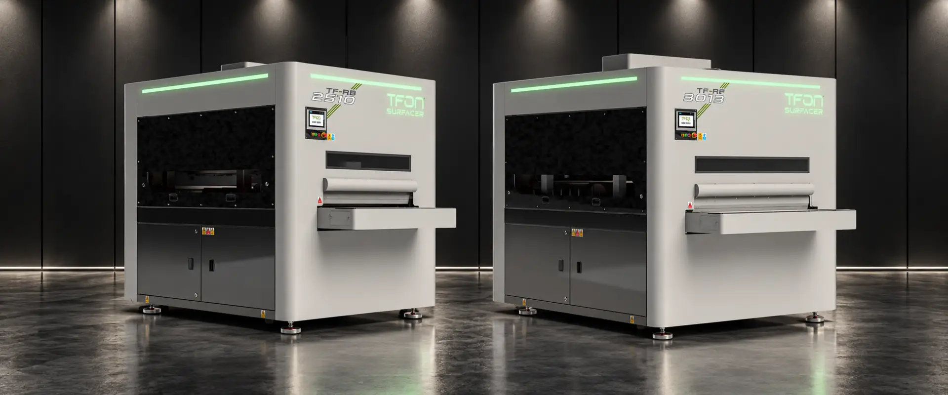
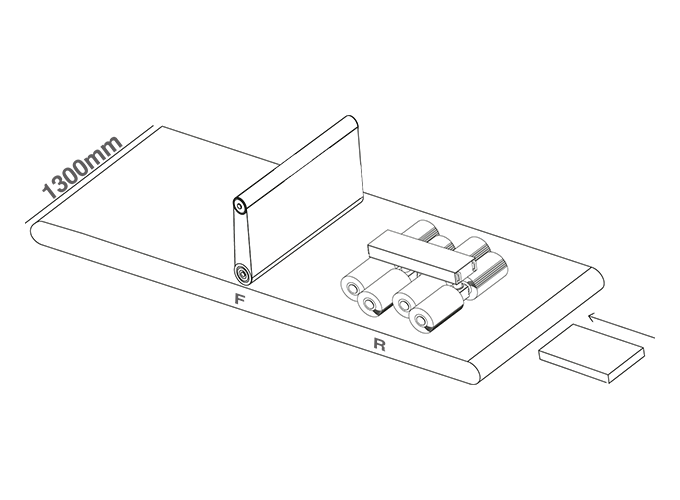
- TFON Surfacer® TF-RF-3013 Surface finishing machine; 1,300 mm working width; abrasive belt 1330x1820 mm plus 8 flap wheels (Ø350 mm) Specifications Request a Quote
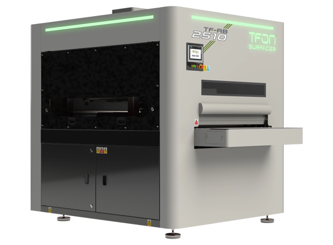
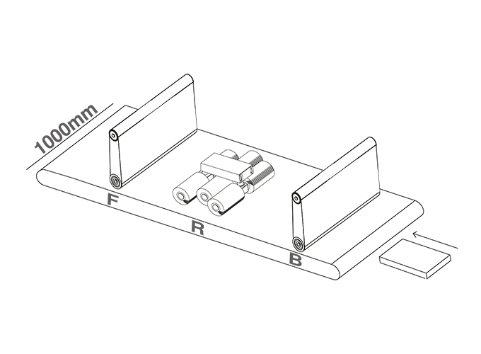
- TFON Surfacer® TF-RBF-2510 Deburring and finishing machine; 1,000 mm working width; abrasive belt 1030x1820 mm plus 6 flap wheels (Ø300 mm) Specifications Request a Quote
What Is Surface Roughness?
Every manufactured surface carries a texture left by the process that made it: the scratches of an abrasive belt, the feed marks of a cutter, the striations on a laser-cut face. Surface roughness is the fine, closely spaced part of that texture. Standards split surface texture into components by wavelength:
- Roughness: short-wavelength peaks and valleys produced directly by the tool or abrasive.
- Waviness: longer, wider-spaced undulations from vibration, deflection or heat.
- Form: the overall shape of the part, such as flatness or straightness. On sheet and plate, form errors are corrected by roller leveling, not by finishing.
- Lay: the direction of the dominant surface pattern, for example the grain of a brushed finish.
A roughness instrument traces a line across the surface and records a height profile. Filters then separate roughness from waviness. The key filter setting is the cutoff wavelength, written λc: undulations longer than the cutoff are treated as waviness and removed from the roughness profile. Parameters such as Ra and Rz are calculated from what remains.
On sheet metal parts, roughness matters for more than looks. It affects how a coating or adhesive grips, how easily a food-contact surface cleans, how a part slides or seals, and how a visible panel reflects light. That is why a finishing requirement on a drawing is usually a roughness value plus a direction, not just a grit number. TFON's page on sheet metal surface finishing covers how those requirements are met in production.
What Is Ra?
Ra is the arithmetic mean deviation of the roughness profile. Take every point of the profile, measure its height above or below the mean line, ignore the sign, and average those values over the measured length. Written as a formula, Ra = (1/l) × ∫ |Z(x)| dx, where Z(x) is the profile height and l is the length over which it is evaluated.
The definition is the same in ISO and US practice. ISO 4287 defined Ra for many years; ISO 21920-2, published in December 2021, has replaced it. In the United States, ASME B46.1 calls the parameter roughness average and uses the same arithmetic-average definition. What differs is the unit. ISO drawings give Ra in micrometers (µm), while US drawings usually give it in microinches (µin). One micrometer is about 39.4 microinches, so Ra 0.8 µm is roughly 32 µin, and Ra 3.2 µm is roughly 125 µin.
What Ra tells you, and what it hides
Ra is stable and repeatable, which is why it is the default roughness parameter on most drawings worldwide. Because it averages the whole profile, a single deep scratch or an isolated burr-like peak barely moves it. Two surfaces with very different profiles can share the same Ra: one with sharp peaks, another with sharp valleys. For a painted panel that may not matter. For a sealing face or a thin coating, it can.
Ra also depends on direction. On a directional finish such as a brushed stainless sheet, a trace across the grain reads higher than a trace along it. TFON's finishing guidance puts it plainly: Ra describes an average of profile deviations; it does not describe every aspect of appearance or every isolated scratch.
A related parameter is Rq, the root mean square of the same deviations. Older US drawings sometimes call it RMS. Rq weights large deviations more heavily and reads higher than Ra on the same profile, so the two are not interchangeable.
What Is Rz?
Rz is the maximum height of the roughness profile. Within one sampling length, add the height of the highest peak (Rp) to the depth of the deepest valley (Rv): Rz = Rp + Rv. Under ISO 4287 and its companion ISO 4288, the reported Rz is the mean of the values from five consecutive sampling lengths. ISO 21920-2 kept this approach for Rz: while Ra is now calculated once over the whole evaluation length, peak and valley parameters are still evaluated on individual section lengths so the results stay stable.
ASME B46.1 in the United States works the same way in principle: Rz is the average of the peak-to-valley heights measured in each sampling length.
Three meanings of one symbol
Rz has changed definition over the decades while keeping the same symbol, which causes real disputes between suppliers and customers:
- Current ISO and ASME Rz: mean of the peak-to-valley heights of the sampling lengths, as above. German drawings built on the former DIN 4768 use essentially this definition.
- Ten-point height: the older ISO definition, averaging the five highest peaks and five deepest valleys in one sampling length. Japanese standards keep it under the name RzJIS.
- Single maximum values: Rt, the total height over the full evaluation length, and Rz1max, the largest single peak-to-valley height.
If a drawing says Rz and comes from an older document or another country, confirm which definition is meant before quoting a finishing operation.
Why Rz is specified
Rz responds to the extremes that Ra averages away. Engineers call it out when isolated peaks can break through a thin coating, damage a seal or cause wear on a sliding surface, or when deep valleys can trap dirt or start corrosion. Rz is common on German drawings, so parts for German customers may carry an Rz value where a US drawing would show Ra.
Ra vs Rz: What Is the Difference?
Ra is an average; Rz is a height. Ra says how far the profile deviates from its mean line on average. Rz says how tall the profile is from its highest peaks to its deepest valleys. On any real surface Rz is the larger number, and the gap between the two depends on the shape of the profile.
| Parameter | What it measures | Sensitive to isolated peaks and scratches? | Typical use |
|---|---|---|---|
| Ra | Arithmetic mean deviation from the mean line | Low | General finish requirement, appearance, coating preparation |
| Rq (RMS) | Root mean square deviation from the mean line | Moderate | Optical and statistical work; older US drawings |
| Rz | Mean peak-to-valley height of the sampling lengths | High | Sealing and sliding faces, thin coatings, German drawings |
| Rt | Total peak-to-valley height over the evaluation length | Very high | Surfaces where a single defect matters |
Converting between Ra and Rz
There is no exact conversion. A common planning estimate is that Rz runs about four to seven times Ra: closer to four on smooth, even surfaces and closer to seven on rough, irregular ones. Some metrology references note that when an Ra requirement is converted into an Rz requirement, the ratio can run well above seven, because a surface that just meets an Ra limit can still carry tall isolated peaks.
Treat any ratio as a rough rule for early planning only. Do not accept or reject parts on a converted value. If the drawing says Rz, measure Rz. If supplier and customer disagree, the practical fix is to measure the same part with the same parameter, filter and cutoff on both sides.
Which one to specify
For most sheet metal appearance and coating work, Ra with a stated direction is enough. Add Rz, or specify it instead, when peaks and valleys matter to function: thin coatings, gaskets, sliding contact or hygiene surfaces where valleys hold residue.
Surface Roughness Values Table by Process
Every process has a range of roughness it normally produces. The table below lists typical Ra values, the band a shop routinely holds, for processes relevant to sheet and plate parts. The process values come from the production-method roughness chart published in Machinery's Handbook; the stainless steel rows come from the finish definitions in ASTM A480 and EN 10088-2. Rougher and smoother results than these are possible under particular conditions.
| Process | Typical Ra (µm) | Typical Ra (µin) | Roughness grades |
|---|---|---|---|
| Flame cutting | 12.5-25 | 500-1,000 | N10-N11 |
| Hot rolling | 12.5-25 | 500-1,000 | N10-N11 |
| Sawing | 1.6-25 | 63-1,000 | N7-N11 |
| Laser (as listed in the chart) | 0.8-6.3 | 32-250 | N6-N9 |
| Cold rolling, drawing | 0.8-3.2 | 32-125 | N6-N8 |
| Grinding | 0.1-1.6 | 4-63 | N3-N7 |
| Barrel finishing | 0.2-0.8 | 8-32 | N4-N6 |
| Electropolishing | 0.1-0.8 | 4-32 | N3-N6 |
| Polishing | 0.1-0.4 | 4-16 | N3-N5 |
| Lapping | 0.05-0.4 | 2-16 | N2-N5 |
| Stainless No. 3 finish (ASTM A480) | generally up to about 1.0 | generally up to 40 | - |
| Stainless No. 4 finish (ASTM A480) | generally up to 0.64 | generally up to 25 | - |
| Stainless 2K satin polish (EN 10088-2) | below 0.5, measured across the grain | below about 20 | - |
Read the table as a starting point, not a promise. A laser-cut face, for instance, varies widely with material, thickness, assist gas and machine condition, and plasma cutting does not appear in the chart at all. ASTM A480 itself notes that roughness readings differ between instruments, laboratories and operators, and that No. 3 and No. 4 results can overlap. When a value matters, measure your own parts.
For the finishes themselves (ground, brushed, satin and edge-rounded) and how each is produced, see our guide to types of metal finishes.
Roughness Grades N1 to N12 (ISO 1302)
Older drawings and many shop charts use roughness grade numbers instead of Ra values. The N-grade system comes from the 1992 edition of ISO 1302. Each step up doubles the Ra value, from N1, a lapped or superfinished surface, to N12, a flame-cut or hot-rolled surface.
| Grade | Ra (µm) | Ra (µin) |
|---|---|---|
| N1 | 0.025 | 1 |
| N2 | 0.05 | 2 |
| N3 | 0.1 | 4 |
| N4 | 0.2 | 8 |
| N5 | 0.4 | 16 |
| N6 | 0.8 | 32 |
| N7 | 1.6 | 63 |
| N8 | 3.2 | 125 |
| N9 | 6.3 | 250 |
| N10 | 12.5 | 500 |
| N11 | 25 | 1,000 |
| N12 | 50 | 2,000 |
The 2002 edition of ISO 1302 dropped the N-grades, and ISO 1302 itself was withdrawn at the end of 2021 and replaced by ISO 21920-1. The grades survive on legacy drawings, so it helps to know them, but new drawings should state the parameter and its value directly, for example Ra 1.6 or Rz 10. The same Ra series (0.8, 1.6, 3.2, 6.3 µm and so on) is still the usual set of preferred values, and it matches the familiar US callouts of 32, 63, 125 and 250 µin.
Surface Roughness Symbols on Drawings
A roughness requirement on a drawing is built on a basic symbol: two lines of unequal length forming a check mark that touches the surface or an extension line. Under ISO 1302 and its successor ISO 21920-1, three variants tell the shop how the surface may be made:
- Basic symbol (open): any production method is allowed.
- With a horizontal bar closing the triangle: material removal is required, for example grinding or machining.
- With a circle in the V: material removal is not permitted; the surface stays as rolled, cast or formed.
The requirement itself is written on a horizontal line extending from the long leg, in the form parameter plus limit value, for example Ra 1.6. It can also carry an upper or lower limit (U or L), filter and evaluation length settings, the production method and a lay symbol. The lay symbols are = (parallel to the view plane), ⊥ (perpendicular), X (crossed in two directions), M (multidirectional), C (circular), R (radial) and P (particulate, non-directional).
What changed with ISO 21920-1
ISO 21920-1 introduced a modified symbol so that a drawing shows which rule set applies. A drawing with the new symbol is read under ISO 21920; one with the old symbol is read under ISO 1302 and its companion standards. The default acceptance rule also changed. ISO 1302 used the 16 percent rule, which let up to one in six measured values exceed the limit. ISO 21920-1 makes the max rule the default: no measured value may exceed the limit.
US drawings
In the United States the symbols follow ASME Y14.36, and values are usually given in microinches. On many US drawings a bare number above the check mark, such as 63 or 125, is read as Ra in microinches. When a drawing mixes units or leaves the parameter unstated, ask before quoting.
How Is Surface Roughness Measured?
Stylus profilometers
The workhorse instrument is the contact stylus profilometer. A diamond stylus is drawn across the surface at constant speed and its vertical movement is recorded as a profile. ISO 3274 sets the nominal stylus geometry: a conical tip with a 60° or 90° cone angle and a tip radius of 2, 5 or 10 µm. Portable units handle most shop-floor checks on sheet metal parts; lab instruments add longer traces and finer resolution.
The cutoff is chosen from the expected roughness. For non-periodic profiles, ISO 4288, now replaced by ISO 21920-3, gives the following defaults. The evaluation length is five cutoffs.
| Ra range (µm) | Cutoff λc (mm) | Evaluation length (mm) |
|---|---|---|
| over 0.02 up to 0.1 | 0.25 | 1.25 |
| over 0.1 up to 2 | 0.8 | 4 |
| over 2 up to 10 | 2.5 | 12.5 |
| over 10 up to 80 | 8 | 40 |
Optical methods
Non-contact instruments, such as confocal microscopes, coherence scanning interferometers and focus variation systems, measure an area instead of a line. They report areal parameters like Sa and Sz under ISO 25178-2. They suit soft or delicate surfaces, but results do not always match stylus readings on the same part, so agree on the method before comparing numbers.
Practical rules for sheet metal parts
- Trace across the lay unless the drawing says otherwise, and record the direction.
- Measure on a clean, flat area away from edges, holes and handling marks.
- Record instrument, stylus, cutoff and evaluation length with every result.
- Use comparator plates only for quick screening, not for acceptance.
- Check edge radius separately; a profilometer trace on a flat face says nothing about the edge. See sheet metal edge rounding for how edges are specified and inspected.
Abrasive Grit and Ra: What Controls the Finish?
No standard maps a grit number to an Ra value. Finer grit tends to lower Ra, but the result also depends on the abrasive type and condition, belt or brush speed, contact pressure, feed rate, the material and the marks left by earlier steps. A fine final stage does not remove deep scratches from a coarse one; each stage has to take out the marks of the one before. In TFON's own words, a grit number alone does not define a finish. Acceptance needs a reference sample or a measured roughness value.
Grit scales add their own confusion. Coated abrasives are graded under FEPA P-grades in Europe and ANSI/CAMI grades in the United States, and the two scales drift apart at the fine end. When a finish is carried over from one supplier to another, compare samples, not labels.
TFON consumables and their grit ranges
- Abrasive belts in aluminum oxide, ceramic and zirconium: grit 40-400. Cubitron belts: grit 24-400. Belt sizes run from 680x1820 mm to 1630x1820 mm.
- Edge rounding flap brushes: grit 60-400, in Ø270x250, Ø300x400 and Ø350x490 mm sizes.
- Scotch non-woven belts: coarse, medium, fine and very fine, for satin finishing.
On a TFON Surfacer, the belt sets the base scratch pattern and the flap or non-woven stations refine it. The TF-RF-3013 surface finishing machine covers a 1,300 mm working width; the TF-RBF-2510 deburring and finishing machine covers 1,000 mm and adds deburring in the same pass. Both run at 0.6-4.0 m/min and work the top face of the part per pass. The full range of deburring and edge rounding machines shows which stations each model carries.
The reliable way to set a finish is a trial: run your parts, measure Ra before and after on the same instrument and in the same direction, and keep a signed reference sample. TFON has not yet published its own before-and-after roughness data, so qualify the result on your material.
TFON Machines for This Job
-
TFON Surfacer® TF-RF-3013
Surface finishing machine; 1,300 mm working width; abrasive belt 1330x1820 mm plus 8 flap wheels (Ø350 mm)
Specifications Request a Quote -
TFON Surfacer® TF-RBF-2510
Deburring and finishing machine; 1,000 mm working width; abrasive belt 1030x1820 mm plus 6 flap wheels (Ø300 mm)
Specifications Request a Quote
Frequently Asked Questions
What is a good Ra value for sheet metal?
It depends on the function. The Machinery's Handbook process chart lists cold rolling at typically Ra 0.8-3.2 µm. ASTM A480 says a No. 4 stainless finish is generally up to 25 µin (0.64 µm). Painted internal parts rarely need a limit at all. Specify the value the part needs for appearance, coating or cleaning, plus the direction of measurement.
Is Rz always larger than Ra?
Yes. Rz is a peak-to-valley height, while Ra is an average deviation from the mean line, so on any real profile Rz is the larger number. How much larger depends on the profile shape. Rz of four to seven times Ra is a common planning estimate, but it is not a conversion and should not be used to accept parts.
What does N7 mean on a drawing?
N7 is a roughness grade from ISO 1302:1992 and means Ra 1.6 µm, about 63 µin. The N-grades were dropped from the 2002 edition of ISO 1302, which ISO 21920-1 has since replaced. You still see them on older drawings. New drawings should state the parameter and value, for example Ra 1.6.
What is the difference between Ra and RMS?
Ra is the arithmetic average of the absolute profile deviations. RMS, now called Rq, is the root mean square of the same deviations. Rq weights large deviations more heavily, so it reads higher than Ra on the same profile. Older US drawings sometimes call out RMS; treat it as a different parameter, not a synonym for Ra.
How is surface roughness measured on the shop floor?
Usually with a portable stylus profilometer. A diamond stylus traces the surface, normally across the lay, over an evaluation length of five cutoffs, for example 5 x 0.8 mm for Ra between 0.1 and 2 µm. Comparator plates give a quick visual check but do not replace a measurement for acceptance.
Does a finer grit always give a lower Ra?
Not by itself. Finer grit tends to lower Ra, but the result also depends on the abrasive condition, contact pressure, feed rate, the material and the scratches left by earlier steps. A fine final stage does not remove deep marks from a coarse one. Qualify the sequence with a reference sample and a measurement.
Let Us Review Your Part
Share the material, cutting method, part dimensions and the next operation, with photos of both faces. We will recommend the machine and station sequence that fits the part.